Eng-Tips is the largest engineering community on the Internet

Intelligent Work Forums for Engineering Professionals

  • Congratulations waross on being selected by the Tek-Tips community for having the most helpful posts in the forums last week. Way to Go!

Steel column hairpin rebar 2

Status
Not open for further replies.

enriko12

Industrial
Sep 5, 2020
54
0
0
US
Hi,

We are working on the old steel building with no original prints available. After contractor removed the old slab, there were hairpin rebars wrapped around column pedestals. I understand their purpose is to provide "some" lateral resistance. Anyone had previous experience with those being damaged/removed and any adverse affects on the structure? How useful are those anyway? It's not like they are going to tie 2 sides of the moment frame together. Control joint are typically cut into interior slabs, so hairpins will rarely tie into more than 1 tile, and sometimes joint are cut right through that rebar. Also, slabs are typically poured last, so those are definitely not helping with any dead weight. I am thinking that single slab tile would add a negligible lateral resistance in comparison to that of the buried spread footing/column pedestal/wall footing.

Any input is highly appreciated!


Replies continue below

Recommended for you

End frames are actually rigid, identical to the rest. Area of interest is in the middle of a building, so that should not make much difference.
 
jimstructures, thanks a lot for the loads. What SW have you used? do you have a list of load cases? Based on reactions, I assume load case 1 is D+L using 20 psf live + 6 psf dead, is that right?
I cant seem to correlate that to the purlins, I am either missing something or original designer used ASCE 7 equation with 0.7 factor: pf=0.7 * Ce * Ct * Is *pg. That would give 14 psf life +3 psf dead (purlins/roof/insulators), not counting the weight of the frame as it does not act on purlins.
I did measure the frame and quick calculations using 17psf (=425 lb/ft on the frames) resulted in 84 kip-ft bending in the middle, causing 24ksi stress which matched up with allowable for A36.

 
seriko12,

I used some proprietary software from a major pemb manufacturer.

What I supplied are the controlling foundation reactions at the anchor bolts.

Since you are not purchasing their building I do not feel comfortable supplying the nitty-gritty of Load cases and Load combinations.

In ASCE 7 parlance Dead Load, etc is a Load Case and Dead Load + Live Load is a Load Combination, just for future reference.

Since this is a PEMB Dead Load, it is approximately 3 psf. over the footprint of the building and Collateral Load is another 3 to 5 psf.

I see that they have used Load Case 1 a little sloppyly or loosely. It is DL + COL + LL or Roof Snow Load (since they were both 20 psf.).

Jim

 
Yes, I meant to say load combinations, sorry. There is no COL at the moment, and no live/snow load, so even with very conservative 5 psf dead load over the footprint, column trust will scale down to 2.7kip which should not be a problem. Now, any ideas on how to restore a full capacity, considering space constraints below? preferably no additional structural elements to be placed in the hatched area:
 
Not correct, there may be no Collateral Load(however imprudent that might be) there is a 20 psf Minimum Roof Snow Load due to the 1/4" in 12" roof slope.

So your horizontal kickout (horizontal reaction) has got to include that part of the load.

I used IBC 2015 because you didn't know what building code was enforced when the building was built. I also used Indianapolis for the home city since you say which county the building was located.

Jim
 
I have no idea what you are talking about as far as restoring full capacity.

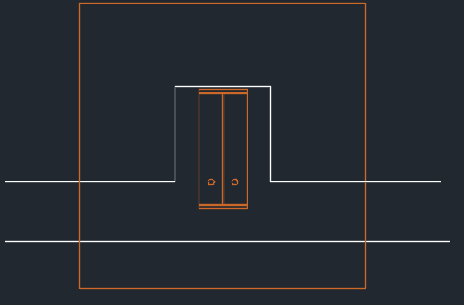
I also have no idea what you trying to show in your sketch. A few more dimensions might help as well as telling us where the sketch is located in the building.

Jim

 
I meant at this point in time (during renovation) there is no collateral load and there is no snow expected for another 3 months. So as a temporary measure during the project, existing foundation should have no problems with resisting sliding/overturning. Now it might or might not be adequate with a full snow load (DL + COL + LL) and ideally I would like to have it taken care of before heavy snow. Here is an updated sketch, the 2 columns are in a middle of the building at 75/0/0. This is the only frame which had the slab removed
area_un0l3b.png
 
Someone just needs to do some calculations on it to resolve the horizontal forces. If the forces can't be dragged into or through the slab, then the foundation will need to be properly designed or reinforced accordingly.
 
Seriko12,

Let me see if I understand what you want to do. You want to design a connection between a renovated slab and a foundation element for a reduced load and then not change it for a permanent load applied to that foundation element when the snow load is later applied? How are you going to increase the capacity for the standard Snow Load when it is going to be applied at a later date?

Jim

 
It seems to me the OP is preparing for snow while the new slab has not yet placed. I think temporary construction supports should be installed throughout the work period.
 
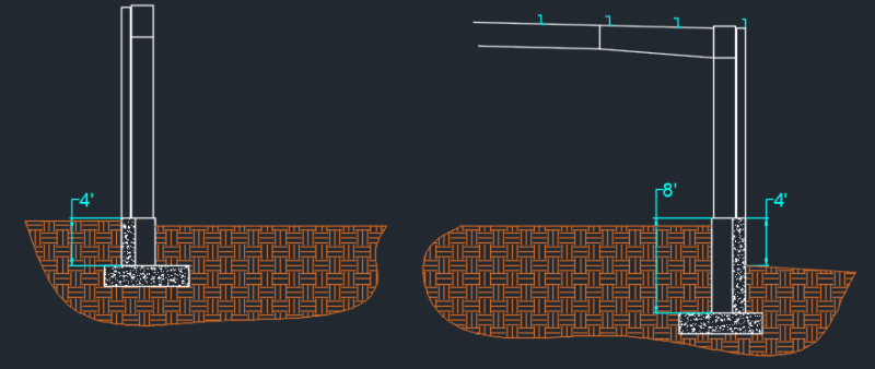
No, the existing foundation alone is fine handling the reduced load, so I want to design a reinforcements for the existing foundation, or some sort of a connection, so it can handle the full load before the building can be potentially exposed to it. Existing footings appear to be 4' x 4', and pedestals and grade wall are 4' tall on the front, and 8' tall in the back. Pedestals are 16" x 16"
footing_zm5ape.png
 
If the foundation wall shown in your most recent sketch is correct your pier is 16" wide (parallel to foundation wall) x 24" deep (perpendicular to foundation wall). Assuming foundation wall is 8" thick.

retired13

I don't think the OP wants to tear out the existing foundation and replace it with a revised new foundation (with a shear key). Please correct me if I am wrong.

Jim

 
I assume the column isn't there at this time. So, a pocket can be created in the existing pedestal to receive a shear key to restore lost shear capacity.
 
Foundation wall is 10" or 12" thick depending on location. So using this approach, piers are 16" x 26" and 16" x 28". Of course we have no idea how the reinforcement was placed, but judging by anchor bolt location, stirrups are probably enclosing those, so you are right about adding wall thickness to the pier. Column is centered over the footing.
Overturning is the controlling load, so shear key would not help anyway
 
The original foundation, anchor bolts, hairpins and columns are intact and in place. Only slab in between is gone and direct path is unavailable due to newly added recessed areas and isolated machinery foundations. There is no plan to tear out and redo the existing foundation. Something can be added onto it though, and hairpins can be tied into something new too.
Without reinforcement details, its hard to guess how much load will get transferred to the foundation wall. With the pier on the inside, it is pushing against the wall, which assumed to have horizontal bars, so shear and sliding are no issue.
But overturning & eccentricity can be. Remember, front pier is 4ft tall and rear one is 8ft tall which creates a significant overturning moment, especially at the rear.
 
Sorry that I didn't read through all the posts before responded to your question. Now I got your point, but still confused on the 4', 8' references of the pedestal/grade beam height. A cross section with backfill elevation shown can clear up the confusion. Before get to that, just to remind you, that without change any of the existing structure, but removal of the slab, you can estimate the original lateral force by calculate the strength of the shear pin, Tu = ØAsfy <= shear capacity of the anchor bolts, then evaluate the stability of the existing foundation.

I am not a fan of utilizing backfill for footing stability evaluation, but for this case, it can be justified.
 
Status
Not open for further replies.
Back
Top