Eng-Tips is the largest engineering community on the Internet

Intelligent Work Forums for Engineering Professionals

  • Congratulations waross on being selected by the Tek-Tips community for having the most helpful posts in the forums last week. Way to Go!

Steel component_Guardrail system base connection 2

Status
Not open for further replies.

engineering3DTEK

Structural
Nov 25, 2021
4
0
0
IN
Hello fellow engineers,
AISC design guide 34
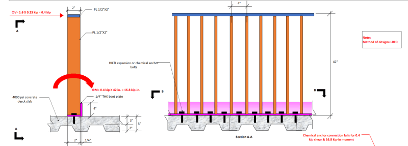
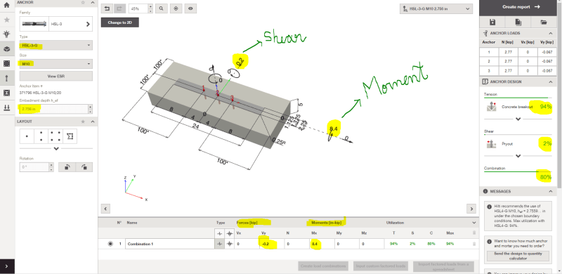
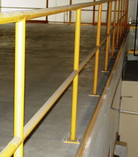
I am designing base connection for a guardrail system. I apply 0.250 kips force on the top rail factored with 1.6 (LRFD), therefore 0.4 kips shear force on top rail. The height of my guardrail system is 42". So I get a moment of 0.4 X42 = 16.8 kip-in momnent at the base connection. But for this force, I am unable to design expansion or chemical anchor base connection. The connection fails. The depth of available concrete slab is just 3" (4000 psi).
Please refer to the attachment (PDF) & image depecting the exact scenario.
Could someone please suggest me how to distribute the forces to anchor bolts & how could I make this connection work.
Thanks you.
Base_connection_Sketch_nhukps.png
 
Replies continue below

Recommended for you

Welcome to the biggest issues with guardrails. The anchorage required is almost never allowed due to how it looks. Can you just drill through the floor completely and install a through-bolt to the underside of the deck?

Are you the EOR or a delegated design engineer in this case.
 
Hello jayrod12 ;
I am the delegated design engineer. I got confirmation from the ARCH on the looks. It is fine for them. What I thought is, maybe I will distribute this 0.25 kips b/w 2 adjacent guardpickets,i.e., Shear= (0.25/2)*1.6= 0.2 kips; Moment= 0.2*42= 8.4 kip-in. When I check for this load critera, the connection passes (refer below snap). Do you think this load distribution which I assumed is correct?
Base_connection_With_reduced_load_lqmxam.png


I think if your governing moment is the point load, and those pickets are spaced that tightly, I don't see why you couldn't count on a couple of anchors helping you out.
 
I'm not following your loading. Can you change some of the assumptions to help out?

I thought it was 200lb point load applied in any direction? Or 50lbs uniform load per foot? Both of those loads would get hit with the 1.6 load factor.

 
I'd distribute the load over a 2' width... to engage about 5 or 6 of them... the BAR 1/2x2 is pretty stiff construction. Anchorage cost will 'kill ya'... and you may want to look at spacing them out to 8". Have to watch out for edge distances with the fasteners; they can generate fairly high bursting stresses and add to your notes that torque shall not exceed manufacturer's recommendations.

Rather than think climate change and the corona virus as science, think of it as the wrath of God. Feel any better?

-Dik
 
I would talk to the person paying you. The pounds of steel and welding seem a tad on the high side. I prefer to attach to the steel below. Solves this problem, and it can be put up with the primary steel. I see you have the slab thickness = 5" in Profis. You will need to be clear that they are to coordinate the holes with ribs or make sure you have 5" regions where needed.
 
With that top rail (1/2" x 2"?), I would think you should be able to distribute the concentrated load over several feet. Calculating the distribution length with the interaction of the verticals is outside my wheelhouse, though.

If you're still having issues with the anchors after figuring a distribution, would it be possible to widen the base to get a larger resisting moment arm?

Rod Smith, P.E., The artist formerly known as HotRod10
 
BridgeSmith... I figured at least over a couple... actually he could space them at 4' and have BAR 1/2x1/2 pickets @ 4" o/c. Anchorage into the steel deck topping may be more problematic.

Rather than think climate change and the corona virus as science, think of it as the wrath of God. Feel any better?

-Dik
 
 https://files.engineering.com/getfile.aspx?folder=ac339bab-ae71-4bef-9492-8f177b51f48c&file=NGuardrail_BAR_No_Base.pdf
I roughly calculated that the top rail bar could span laterally unsupported up to 10' without yielding, but I'd have to think a little harder on how the pickets affect the load distribution to the angle and anchors at the bottom...

Rod Smith, P.E., The artist formerly known as HotRod10
 
Hello engineers,
Thanks you for your valuable points.
The information regarding the deck slab which I mentioned in yesterday's attachment is incorrect. It is actually a 12" THK concrete slab w/ reinforcement. So I have enough depth to provide a good 6" embedment. My major concern was only the design of the anchor connection and not the design of top rail or vertical pickets. They are well designed to resist the factored (LRFD)horizontal force (0.4 kip) & moment (16.8 kip-in).

So as @dik said, I thought perhaps distributing the point load (governing load) at every 2'-4" for the purpose of design of anchor connection only. And the connection works fine. I placed 3 chemical anchors @ 12" c/c spacing in a 2'-4" span base plate. The anchors were capable of resisting the horizontal force & the moment. I was able to reduce the no. of chemical anchors too rather than providing b/w every picket (@ 4" c/c).

Please refer to the attachment & let me know your thoughts.
 
 https://files.engineering.com/getfile.aspx?folder=96e8bdd1-aac1-439a-930e-9cd4cd7d6ae9&file=Base_anchor_connection_design.pdf
Looks like you are using a rigid body load distribution assumption. What happens to your anchor loads if you choose the flexible FEM-based base plate option in Profis? I’m guessing the outer anchors would have less tension and the central anchor would be greater.
 
If you have any FEA software you can easily create a model to look at the forces. It took about 10min to model a 48" long region of the assembly using shell elements. So long at the pickets are welded at the base and vertical face of the angle I suspect it is quite stiff. With a 12" slab I would look to use fewer larger anchors.

EXTRUDED_eavj7g.jpg


RXN_h6fsdg.jpg
 
Whatever you end up doing, I would recommend you consider the viewpoint of the end user/GC/common man. They are used to seeing guardrails like the one below that probably weren't even engineered but that function perfectly. Requiring an anchor every 4 inches looks ridiculous by comparison and could make you look out of touch with reality. I think it comes down to your assumptions being way too conservative. A different way to think about it is that no matter how good your theory is, if it doesn't match the experimental results, it's wrong. In this case there are millions of guardrails like the one below performing all over the world. If whatever you end up calculating doesn't agree with those experimental results, you need to change your theory.
Industrial_Guard_Rail_pcvtwe.jpg
 
You can weld the kick plate to the bottom plate to make it an angle section, for even greater stiffness. [lol]

Rather than think climate change and the corona virus as science, think of it as the wrath of God. Feel any better?

-Dik
 
Be careful when using Profis. Note that Profis distributed the load equally to each of your fasteners. This is likely not be the case and is not a conservative assumption. Don't let Profis tell you how the structure acts - you tell it.

Also, you need to consider your worst case. Usually it's when the load is applied to the very end of a run of rail. The forces might not distribute out nicely like it does when applied to the middle of a run.
 
Rather than guess at how the load is shared between adjacent posts, I use the procedure in NAAMM AMP 521-12 that distributes the load based on stiffness and number of adjacent spans. Unless your endpost is attached to a wall, it's always going to control since it will never shar much with adjacent posts.
 
You mentioned the architect was fine with the look. If you’ve got that freedom, you should be able to present a design for them to consider which may be more conventional using intermittent posts, square base plates having (4) anchors, top & bottom rails, steel pickets and a toe kick.
 
Status
Not open for further replies.
Back
Top