neukcm
Structural
- May 3, 2015
- 63
Hi Everyone!
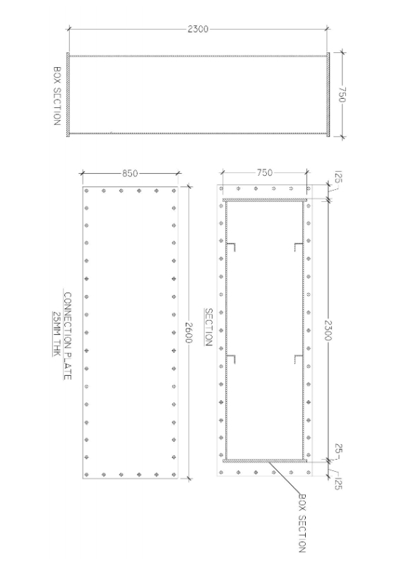
This is a novel-like question regarding the analysis and design of steel connection based in Euro Code, configuration as per attached. A deep box section connected to another deep box section using bolted end plate.![[smile]](/data/assets/smilies/smile.gif "[smile] [smile]") . I've been reading and trying to understand EN 1993-1-8 but it focuses mainly on I shape sections and that hollow sections limited to truss members.
. I've been reading and trying to understand EN 1993-1-8 but it focuses mainly on I shape sections and that hollow sections limited to truss members.
Objective: To determine the least resistance of the connection (TENSION,COMPRESSION,SHEAR & MOMENT)considering all components - bolts, welds, end connection plate, box flange (top & bottom plate) and box web (side plate)
1. For Tension Resistance:
1.a. Bolt Tension - calculated using established formula from table 3.4 EN 1993-1-8:2005, add the total bolt tensile capacity and check with the design Tensile force.
1.b. Weld Tension (box web & flange) - calculated by means of software.
1.c. End Plate Tensile Capacity - neglected.
1.d. Box Web Tension (Side Plate) -neglected.
Question: Resistances of components 1.c and 1.d were neglected and as a result, bolts or welds tension capacity governs(whichever is lesser). Anyone here who has an idea of how to calculate those neglected resistances, manually or by means of FEA? I understand that plate yielding must be considered in the connection as it might give less resistance than that of the bolt or welds.
2. For Compression Resistance
2.a. Box web compression -neglected.
2.b. Box web weld - calculated by means of software.
Question: Again, resistance of component 2.a was neglected, plate yielding out of equation, the compression resistance of the connection will be that of the welds. Any suggestion on how to determine the compression capacity of plate?
3. For Shear Resistance (Horizontal/Vertical)
3.a. Bolt Shear - calculated using established formula from table 3.4 EN 1993-1-8:2005, add the total bolt shear capacity and check with the design horizontal/vertical shear force.
3.b. Bolt Bearing (Connection plate & Box Flange) - same procedure as 3.a.
3.c. Box Web to Connection Plate welds - calculated by means of software.
- No further question for Shear Resistance-
4. For Moment Resistance
- By elastic method, determine the Neutral axis of the section, take the summation of tensile Forces of bolts (in tension zone) to the box bottom flange and compare the result to design moment force.
Question: Is my assumption correct? If not, how will you compute for the moment capacity of the connection?
We have our usual software for this type of connection but is limited in no. of bolts and size of connection plate. This section is too large and we even have 5-6 meters connection plate with very deep box which the software is not able to analyze anymore resulting to tedious manual calculation. I have came across forums about Eurocode and in some software developers but unfortunately no one dares to explain to me how. I know the only issue was about plate yielding but i have it itemized for clarity. Thanks once again!!
cheers,
NEUKCM
Structural Design Engineer
This is a novel-like question regarding the analysis and design of steel connection based in Euro Code, configuration as per attached. A deep box section connected to another deep box section using bolted end plate.
. I've been reading and trying to understand EN 1993-1-8 but it focuses mainly on I shape sections and that hollow sections limited to truss members.Objective: To determine the least resistance of the connection (TENSION,COMPRESSION,SHEAR & MOMENT)considering all components - bolts, welds, end connection plate, box flange (top & bottom plate) and box web (side plate)
1. For Tension Resistance:
1.a. Bolt Tension - calculated using established formula from table 3.4 EN 1993-1-8:2005, add the total bolt tensile capacity and check with the design Tensile force.
1.b. Weld Tension (box web & flange) - calculated by means of software.
1.c. End Plate Tensile Capacity - neglected.
1.d. Box Web Tension (Side Plate) -neglected.
Question: Resistances of components 1.c and 1.d were neglected and as a result, bolts or welds tension capacity governs(whichever is lesser). Anyone here who has an idea of how to calculate those neglected resistances, manually or by means of FEA? I understand that plate yielding must be considered in the connection as it might give less resistance than that of the bolt or welds.
2. For Compression Resistance
2.a. Box web compression -neglected.
2.b. Box web weld - calculated by means of software.
Question: Again, resistance of component 2.a was neglected, plate yielding out of equation, the compression resistance of the connection will be that of the welds. Any suggestion on how to determine the compression capacity of plate?
3. For Shear Resistance (Horizontal/Vertical)
3.a. Bolt Shear - calculated using established formula from table 3.4 EN 1993-1-8:2005, add the total bolt shear capacity and check with the design horizontal/vertical shear force.
3.b. Bolt Bearing (Connection plate & Box Flange) - same procedure as 3.a.
3.c. Box Web to Connection Plate welds - calculated by means of software.
- No further question for Shear Resistance-
4. For Moment Resistance
- By elastic method, determine the Neutral axis of the section, take the summation of tensile Forces of bolts (in tension zone) to the box bottom flange and compare the result to design moment force.
Question: Is my assumption correct? If not, how will you compute for the moment capacity of the connection?
We have our usual software for this type of connection but is limited in no. of bolts and size of connection plate. This section is too large and we even have 5-6 meters connection plate with very deep box which the software is not able to analyze anymore resulting to tedious manual calculation. I have came across forums about Eurocode and in some software developers but unfortunately no one dares to explain to me how. I know the only issue was about plate yielding but i have it itemized for clarity. Thanks once again!!
cheers,
NEUKCM
Structural Design Engineer