Eng-Tips is the largest engineering community on the Internet

Intelligent Work Forums for Engineering Professionals

  • Congratulations waross on being selected by the Tek-Tips community for having the most helpful posts in the forums last week. Way to Go!

steel frame - column to beam connection

Status
Not open for further replies.

greznik91

Structural
Feb 14, 2017
186
SI
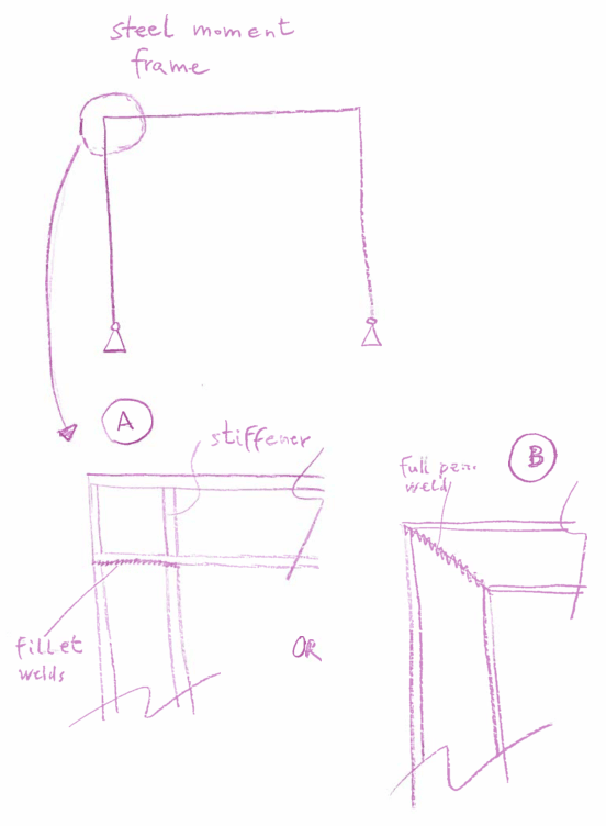
How stiff is a moment steel frame with full penetration weld between column - beam (sketch B) compared to a connection shown in case A where beam is welded to a column with stiffeners. When to use connection B over A? I am not a fan of connection B - I think Id use it only for frames that are not that loaded?

frames_v9fxn5.png
 
Replies continue below

Recommended for you

OP said:
I am not a fan of connection B - I think Id use it only for frames that are not that loaded?

I agree. The main difficulty with option B is that, as the flange forces turn the corner of the joint, there isn't much -- depending on the direction of load -- keeping them from:

1) Pulling off from the web in tension;
2) Buckling into the web in compression.

For small loads, I'll sometimes use option B but consider only the web as resisting moment. Obviously, that makes for a pretty small capacity.
 
If the loads are light, I'd still go for option A and maybe try to justify removing the stiffeners. Option B is a lot more work - you have prep the ends of both beams for the full pen welds. Option A is all square cuts and fillet welds. I'm not an estimator, but I suspect option A is comparable in cost to option B even with stiffeners.
 
I don’t like Option B - but it can work provided you check everything.

My preference would be a bolted version of Option A. That way its easy to transport and your critical connection is not reliant on a site weld.
 
Option A creates an over-strength joint. if the frame fails, it wont be at the corner. With a strong column, weak beam, and a reduced beam section 200-300mm in from the joint and you have a beautiful frame that is the essence of capacity design. you can take advantage of huge reduction factors.

Option B creates a stiff, brittle joint that will likely fail at the joint.

Option B is very common in New Zealand residential construction. This shocked me to see, after all the recent earthquakes and issues
 
I have seen similar to option B in moment frames. See the photo - it has steel plates welded to the end of each beam, and they are connected at approx 45 degrees. You can’t see well in the photos, but the outside corner has the plates extended beyond the beams about 6”, and another set of bolts beyond the top flange (an “extended plate” connection I think it is called). This Photo is from Houston, Texas (USA) and the building is I would guess from the 1980s and has withstood quite a few hurricanes.

--Luke
Texas PE
Structural and Civil Engineering
www.framestudio.com
 
 https://files.engineering.com/getfile.aspx?folder=87263875-8c6d-4359-97b1-3e6affe11d9b&file=1AFE1A6A-5DF4-427D-8ECA-0E6C8F755AA3.jpeg
I don't understand why you would ever do option B. It seems like it's a fundamental misunderstanding of how the loads are moving, with the designer trying to provide continuity of flanges rather than load transfer. You have a trickier cut and harder fitup, with worse restraint because your flange isn't continuous across the connection to restrain web crippling. Option A without stiffeners (or with an end plate or stiffener near the edge of beam) should be used anywhere you would consider using option B. You can flip it so that the beam frames into the column if that detail works better for a specific situation.
 
KootK brings up an interesting point, the Option B detailing is often seen on a steel stair stringer where the stringer transitions from diagonal to horizontal at a landing. You've all stated legitimate reasons to stay away from Option B; what makes it acceptable for the stair connection? Is it simply that the smaller angle of turn (25 - 40 degrees instead of 90 degrees)? Or other factors?
 
Non 90 degree corners are going to require some sort of mitered joint. For angles under 45 degrees from parallel, the conventional style of stringer mitered connection makes sense. At higher loads, you could consider some stiffeners to deal with load transfer, but this is a typically low load situation.
 
In trying to visualize what you would check for Option #B. Would you just break the force into a vector at the joint and have a diagonal thrust essentially at the corner and check the web for buckling, etc for the force similar to a standard moment connection without stiffeners or is there something else I am missing? I agree with others it's not a good detail, just want to make sure I understand how it would behave. Would welding a diagonal stiffener at the joint make it better? Or diagonal end plate that each I beam is welded to?
 
I've only ever generally seem option B used with a diagonal stiffener (even in NZ), you can at least justify that arrangement for transferring the bending loads in the member around the corner. Though if you are relying on the column and beam to restrain each other the detail is a bit harder to justify the degree of member restraint provided to each member vs the other.

Very much prefer option A though given a choice.

For larger loads with or without a stiffener for option B, I am really not to sure how you would go about justifying the panel zone as typically you are transferring the forces between two parallel stiffeners or flanges. This situation just isn't present with the mitre cut. I guess diagonal stiffener could be designed for the panel force as there are methods for using diagonal stiffeners in place of doubler plates for example.

For stairs where the angle change is typically less than 45 degrees, I only detail the cranks with a stiffener as well as a matter of good detailing.

I design these stiffeners using code load bearing stiffener provisions to take the out of plane component of the flange tension and compression forces that's parallel to the mitre cut/stiffener.

For smaller loads and no stiffener I've also previously taken just the web as resisting the bending and ignored the flanges like Kootk mentioned earlier in the thread.
 
Status
Not open for further replies.
Back
Top