Eng-Tips is the largest engineering community on the Internet

Intelligent Work Forums for Engineering Professionals

Stepper Motor Time to Speed

Status
Not open for further replies.

sreid

Electrical
Mar 5, 2004
2,127
0
0
US
This question is mostly for the Math Smiths. We will be using one of our servo amplifiers to micro step a two phase stepper motor. The customers controller creates sine and cosine current commands, we supply two current loops.

The amplifier is a linear amplifier so the customers sensors don't get corrupted by PWM switching noise and as always, one wants to minimize power dissipation in the amplifier.

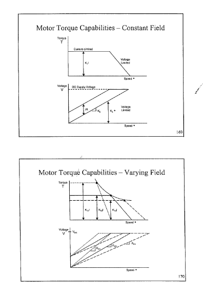
One can use maximum phase current up to the speed where you run out of B+ voltage to over come the motor BEMF and the voltage required to drive current into the phase inductance. Above that speed you can still accelerate but with reduced current.

So one needs to keep the voltage requirement constant as the speed increases but as the current goes down the acceleration decreases and so does the rate of change of velocity.

I see this as "The Rocket Velocity Problem" where the thrust decreases as the rocket velocity increases but at the same time the mass of the rocket decreases as the fuel is burned. So I can state the problem but have lost the math skills to solve the problem let alone even come up with the equation for velocity vs. time.
 
Replies continue below

Recommended for you

Does the thrust really decrease with speed (in rockets)? I don't think so.
That misconception may be blurring your vision.

In my world, operating a stepper is very much the same thing as the U/f ratio concept when running an ASIM (or synchronous) from a VFD. You normally keep volts per hertz ratio constant and at nominal value. Not much math needed for that.

When you increase speed (frequency) above the maximum voltage, you cannot keep U/f constant any more as frequency increases, so the U/f ratio drops as speed increases. When U/f drops, so does available torque. And the ratio is, of course, still U/f. The reduced torque is then inversely proportional to speed. At least for practical purposes.

Instead of having a constant torque machine, you then have a constant power machine. Power is k times speed times torque and if torque falls with 1/speed, your equation will become Power is k times Speed times Torque(function of speed). Plug in Torque is 1/Speed and get Power is k, a constant that depends on all parameters like thermal capability, rated voltage, current, speed, torque, cooling, ambient temperature etcetera. Simply put: P=k when above the rated speed and voltage. That math is still extremely simple. No math at all, as I see it.

There is no need to complicate it any further - if you do not study transient behaviour on a microseconds (inter-period) time scale. Then, you may need all the math you once learned. And perhaps some more. Electricpete can help you there. And a few other guys in this forum.

Gunnar Englund
--------------------------------------
Half full - Half empty? I don't mind. It's what in it that counts.
 
Skogsgurra,

From "Thrust" in Wikipedia;

1) A rocket is propelled forward by a thrust force equal in magnitude, but opposite in direction, to the time-rate of momentum change of the exhaust gas accelerated from the combustion chamber through the rocket engine nozzle. This is the exhaust velocity with respect to the rocket, times the time-rate at which the mass is expelled, or in mathematical terms:

T = v(dm/dt)

Where T is the thrust generated (force), dm/dt is the rate of change of mass with respect to time (mass flow rate of exhaust), and v is the speed of the exhaust gases measured relative to the rocket.

2)In micro-stepping a step motor, maximum current is always applied where maximum current is the positive or negative peak of the sine and cosine phase currents. Maximum torque is then always available whether it's needed or not. The speed of the motor is controlled by the frequency of the sine and cosine currents. The current may be turnsed off when stopped and no torque is required. Very ineffecient but simple. And because they typically have 100 poles they have high torque at low RPM. Almost a motor plus a gear box.
 
"relative to the rocket" not the speed of the rocket. So thrust remains constant.
Mass is reduced as fuel is consumed. Yes. And that doesn't change anything. The mass (inertia of the motor and load) does not change.

So, there I think that you need to rethink.

If current were constant - then you would not have the problem with the change from constant torque to constant power. The problem is, as you said, that the B+ voltage is limited. And cannot force constant current through the coils.


Gunnar Englund
--------------------------------------
Half full - Half empty? I don't mind. It's what in it that counts.
 
I think that you may be confusing terms and effects.
Above rated frequency you can not maintain the Volts per Hertz. Ratio. The effective impedance of the motor increases as the frequency increases and the increased impedance limits the current.
But, an increased load will cause the current to increase.
Back EMF is also important. As the load lessens the BEMF approaches the applied voltage. Shortly after the load becomes negative, the motor goes into regeneration. The current becomes negative. This happens with overhauling loads.
In the absence of a path for the regeneration current, bad things may happen. Overspeed damage and/or over voltage damage are both possible.


Bill
--------------------
"Why not the best?"
Jimmy Carter
 
sreid:

Here are the plots I have used in the past to explain these limitations to students:

Motor_Torque_Curves_b1bhmp.png


On the "Constant Field" slide (all we will consider here), I show the torque/speed diagram that people are used to seeing, especially for DC motors. Below that I show the matching voltage/speed plot that "explains" the torque/speed plot. The lower line on this plot is the Ke*w back EMF. The gap between it and the upper line is shown as the "IR" drop, but in the more general case includes the L*di/dt voltage as well.

You are correct that you cannot get as much acceleration when you approach top speed as you can at low speeds. In the past, I would see it recommended to use a parabolic velocity profile if you really wanted to maximize your acceleration to top speed. I think now most people use an "S-curve" velocity profile instead for the sake of smoothness when starting, but keeping the parabolic velocity profile (decreasing acceleration) as maximum speed is reached.

A couple lesser points:

The difference between your linearly modulated amplifier and the more common pulse-width modulation is not important for this behavior.

If you are using a 3-phase servo-motor amplifier for your 2-phase stepper motor by tying two of your motor leads to the same amplifier output (quite commonly done), your effective bus voltage is reduced by a factor of 1/sqrt(2), so you really have only 70% of the bus voltage available.
 
Status
Not open for further replies.
Back
Top