Continue to Site

Eng-Tips is the largest engineering community on the Internet

Intelligent Work Forums for Engineering Professionals

  • Congratulations KootK on being selected by the Eng-Tips community for having the most helpful posts in the forums last week. Way to Go!

Stiffened HSS End Plate 1

Status
Not open for further replies.

DerekRChristian

Structural
Feb 21, 2019
9
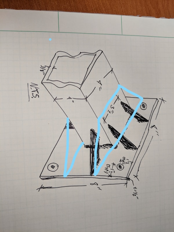
I can't for the life of me figure out how to correctly model and analyze this connection. I have a 4x4x3/8 square HSS tube with an 8x8xx1/2" plate fillet welded to the end.
This plate is then bolted at the corners to the main structure. I've attached a sketch.

Unstiffened, the plate is overstressed almost 200%, but I need to take the stiffeners into account. How can I figure this out?
 
 https://files.engineering.com/getfile.aspx?folder=fb63e05a-d5b5-48dc-8c87-5cb87e43caff&file=IMG_20190221_140503.jpg
Replies continue below

Recommended for you

Most efficient way of dealing with this would be to increase your plate thickness - slightly more material but your labor is essentially the same. Adding gussets will keep your plate thickness down, but now you have more material in the gussets and your labor just went way up. If you're 200% overstressed with a 1/2" plate, a 3/4" plate should do it.

If you need to go with stiffeners, I wouldn't arrange them as you have shown. If you weld to the face of the wall then you're attaching to a soft spot on the section and it will be inefficient. I suggest gussets as shown below. The bending in the plate becomes a simple check as well.

InkedIMG_20190221_140503_1__LI_x4ibb3.jpg
 
Thanks for the input. The connection is already constructed. I'm running an analysis to see if it needs to be modified or anything.
I'll need to back it up with calculations.
 
Totally agree with CANPRO, the stiffeners he shows would be a much better configuration. But, assuming you have to do it the other way.

1) RISA no longer sells it (because they want you to buy a more expensive program that isn't as good for base plates), but the old RISABase (if you can get hold of a copy) might do a good job of analyzing the base plate for you.

2) Then for analyzing the connection of the stiffeners to the side wall of the HSS, you should check out the Chapter 9 of AISC 15th edition. There's a section on plate elements subject to out of plane loads. Not your exactly situation, but you may be able to use it as a starting point.

3) In addition, the AISC design guide on vertical bracing connections (29?) has a design example with a gussett coming into the web of a wide flange. It uses similar yield line formulas to come up with the web's capacity to hand the force. Again, not your exact situation. But, between this and item 2 above, I imagine you can come up with something that's reasonable and conservative.
 
Is it just fabricated already, or is it installed on site? If on site already, access will be key in your reinforcing detail. What is this attached to? Maybe you can add more fasteners in the plate closer to the HSS and avoid welding new gussets.
 
It's installed on site. See the attached photo for an example of what the structure looks like. It's installed on a monopole cell tower. Adding bolts could work, but I'd still need calcs to prove that the existing stiffeners aren't adding enough capacity to resist the bending in the plate.
 
 https://files.engineering.com/getfile.aspx?folder=cb0c3659-5c7f-441e-81dd-508de6c3dde7&file=Platform_Mount.jpg
Ah so the stiffeners are already installed! You didn't mention that before...we're getting to the good stuff now. If you post a proper sketch of the baseplate showing the member size/location, stiffener size/location, and anchor size/location...along with some loads, you'll get more help.

Based on the information given, I'd take the following approach:

[ul]
[li]start with the assumption that the plate/stiffeners are stiff enough to proportion the load equally to all anchors (if anchors/stiffeners equally placed)[/li]
[li]Use a yield line analysis or tables from Roark's if applicable, to check the plate in bending between nearest stiffeners/HSS[/li]
[li]after you evaluate the plate bending in various locations, you can revisit your assumption above. Yield line won't give you a deflection in the plate, but you can use your judgement based on how close you are to yield[/li]
[li]estimate the total load in each stiffener[/li]
[li]Treat the stiffener to HSS connection as a shear tab with axial/shear/moment and check using your favorite/governing HSS design reference. Options - > AISC DG 24, HSS Connection design guide by J.A. Packer and J.E. Henderson, CIDECT design guides. If you or any one else has anything to add to that list of references, I'd love to hear it.[/li]
[/ul]

 
Just out of curiosity what are the size of the antennas you are putting on this mount? At least for my area most low profile mounts have the main cantilever tube as a HSS4x4x1/4 and that rarely fails. The only time I see HSS4x4x3/8 tubes failing is if you are checking a mount for one of the new mount load ratings?
 
Derek, not sure what program you are running, but I had a similar problem last year with a low profile mount and I took the nonlinear way to check the connection to the ring collar. I modeled the stiffeners using RISA plate elements. At the end of it I still had to add a kicker under the low profile mount.
 
 https://files.engineering.com/getfile.aspx?folder=f7ebd333-0809-4a71-a9be-946b488d5cce&file=3in_Pipe_with_Stiffeners.PNG
I'm using RISA3D. I've never modeled anything like how you did, though.
 
The double stiffeners will be pretty easy to account as they're relatively in line with the tube walls. See Omer Blodgett's Design of Welded Structures etc.

The single stiffeners are tricky in addition to being inefficient. I like to keep it stupid simple unless I've got gobs of fee, or some other motivation, prompting me to do otherwise.

c01_glqnye.png
 
If you have never used the plate elements before, first thing I would recommend is watch the video RISA has online about their plates. RISA has some suggested ratios on the plate shapes. I would also be sure to talk to RISA support team and show them the model to look over. Interpreting the results can be tricky and takes a good bit of engineer judgement.
 
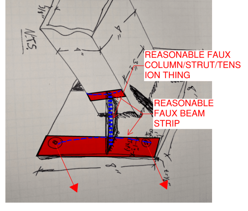
kootk, in your "strip" method, do you have concerns about relative stiffness between the adjacent stiffeners? I like the method as a quick and dirty check, but I'd be inclined to neglect those side stiffeners all together. The stiffeners located on the corners of the HSS are much closer to the anchors, and stiffer...I'd assume they're doing a large majority of the work.

I wish there was a way to tag people in some way to get their opinion on matters...I would love to hear JoshPlum's opinion on ENGINEER92's use of Risa3D to model the stiffened baseplate.
 
Are there going to be "leveling nuts" on the underside of the plate? [shocked]
 
CANPRO said:
kootk, in your "strip" method, do you have concerns about relative stiffness between the adjacent stiffeners?

I do. But, out of practical necessity, steel connection design needs to be based on:

1) A rational, assumed load path that satisfies equilibrium and;

2) Hopefully no plausible, brittle failure modes along that path.

#2 usually winds up being at least partially BS but, alas, life must go on. Unless we're optimizing a "product", I try to stay away from FEM. It's labor intensive and given the uncertainties regarding substrate and anchor behavior, I rarely feel that the apparent precision is justified.

CANPRO said:
I like the method as a quick and dirty check, but I'd be inclined to neglect those side stiffeners all together.

Fine by me. My approach in a non-product scenario would be to start with the simplest method requiring the least dubious assumptions and then work my way into more complex analyses only if required. I went a little astray here assuming that OP could handle the in-line stiffener business on her one and only needed help with the mid-wall stiffener scenario. Gotta watch those assumptions.

CANPRO said:
The stiffeners located on the corners of the HSS are much closer to the anchors, and stiffer...I'd assume they're doing a large majority of the work.

I see what you mean. I'd originally trusted in the to-scale-ness of the sketched but, reviewing the dimensions, I see that you're probably right. Regardless, I'd still start with your method for simplicity and then proceed to mine if I need to milk a little more out of it. Note that the distribution may be different when the base plate under the single stiffeners are in compression depending on the leveling nut situation etc.
 
Connections can be tricky to model with FEM. There is just so much connection testing out there that doesn't necessarily match up with FEM models. I'm reminded of the slotted web WF connections (tested in Arizona) that were tested extensively as an effort to replace the pre-Northridge connections. If I recall, they tested a number of different variations to try to relieve some of the localized stresses by slotting the column or beam webs. And, the testing never quite lived up to what they predicted using FEM.

Some thoughts about the use of FEM for this type of connection and such:

1) Engineer92's model looks like it's well put together. Hard to tell for sure because there are some limitations to the way RISA renders that makes some things look a little odd in that view.

2) Models like this are best for getting LINEAR results. Meaning that you don't take into account any material nonlinearity. Maximum elastic stress on welds and such. Reasonable for connections that remain essentially elastic through their design life. But, I wouldn't rely on these FEM results to justify something that has significant ductility requirements for seismic loading. R = 3, okay. But, certainly not for SMF, IMF, or SCBF. Probably not OCBF, maybe OMF.

2a) There can be some non-linearity associated with compression only springs at the base plate, but not with any material yielding. I should point out that for pre-tensioned bolts, this is also tricky to model in that there would be compression between the main plate and the adjacent flange / plate to which it is connecting.

3) The RISA plate analysis is not capable of checking buckling. For members and the wall (which is a super-element), the program will account for some P-Delta effects when requested, but not for the pure plate elements. Therefore, you'd want to check the b/t ratios for the stiffener plates to make sure they are reasonable. I believe the AISC design guide on stiffened end plate connections has an example where they check the b/t ratio of the stiffener plate to make sure it isn't subject to local buckling.

The biggest concern about this particular connection I have is related to what everyone else has pointed out. Where those stiffeners connect to the approximate middle of the HSS. My thoughts on that.

4) The RISA model may do a decent job of predicting the maximum elastic stress at these points. Of course, this may end up being a little over conservative.

5) In addition, AISC Table K1.2 has a formula (K1-3 in the 14th edition) t_plate < Fu_HSS * t_HSS / Fy_plate. The idea is that you want plate to start yielding before it can rupture through the wall of the HSS.

6) I would do something similar to what KootK did for where the stiffener connects to the HSS. Meaning, I would use a representative length of the stiffener. However, I'd personally prefer to take the stiffener force and convert it into a shear and a tension on connection between the HSS wall and the representative stiffener length. Then I'd use the Table K1.2 equations to check it. That way, it's a little more code based and hopefully a little less conservative than KootK's method.

7) I'm not as concerned over the plate failure strip that KootK has in his drawing. Still worth checking. But, I'd say it's more like a fixed / fixed beam at each bolt location.... assuming that the bolts are fully tensioned and the design strip width isn't much bigger than the nuts / washers in that connection. Though I would want to check that the total reaction at each bolt isn't going to overcome the pre-tension.

 
Instead of individual plate stiffeners, HSS stiffeners (cut from an HSS 3x3) could be used on all four sides of the HSS 4x4. That would provide a stiffer base than the detail shown. The corners of base plate could then be checked using Yield Line Theory.

BA
 
Im no structural engineer but could you add 20mm sq plate washers in each corner of the base plate
and make them almost touch the stiffeners. put one under bolt head and one under the nut.
 
Status
Not open for further replies.

Part and Inventory Search

Sponsor