Eng-Tips is the largest engineering community on the Internet

Intelligent Work Forums for Engineering Professionals

Stiffener Rings 1

Status
Not open for further replies.

BZ29

Mechanical
Jul 26, 2010
37
0
0
SA
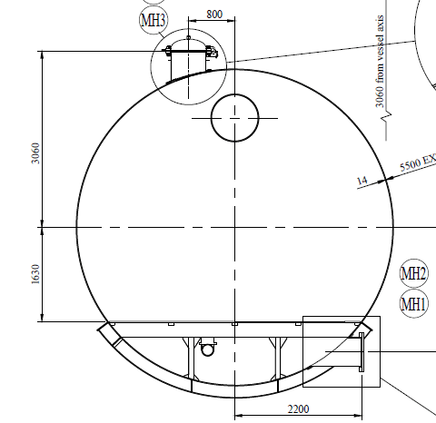
Received some pressure vessel drawings, having following data

ASME Sec VIII Div.2
Dia: 5500mm
Lenght: 20200mm
Thickness: 14(Shell) / 10(heads)
Hemispherical heads
supported on 3 saddles.
Vessel have internals of more than 20000kg

tempsnip1_annjkj.png


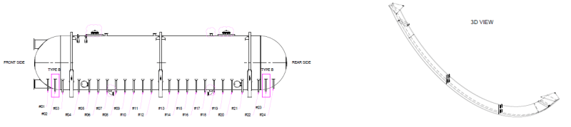
Although design is not in my scope of work, just curious to know, is there any guide or method to calculate these kind of partial stiffener rings (24 rings shown in drawing)?

I have checked myself, and without these partial stiffener rings, vessel design fails due to high circumferential stresses at tip of stiffener.
 
Replies continue below

Recommended for you

I have never seen partial stiffener rings like that before, only full stiffenrer rings for vacuum service. Looks kinda wierd. I imagine they did a FEA and determined that the stiffener rings worked to get longitudinal bending stresses down to within allowable since circumferential hoop stress determines wall thickness of vessel, and should be same on top as bottom of vessel except for small hydrostatic head for any liquids, but seem counter intuitive that circumferential rings would help longitudinal stresses. I would ask the supplier for his calculations and reasons for the stiffeners.
 
These are likely related to supporting a vessel of this size & weight (i.e. for longitudinal bending stresses). The weight of the internals is substantial. You can see the three saddle supports are reinforced with stiffening rings as well. Ideally you'd want to design your saddles to handle all the load combos without having to add dozens of additional stiffening rings like they did, but they may have run into issues with this. I'd ask to check their saddle support calcs and understand their basis.
 
Snickester, Krausen: Thank you for your insights.
Yes it is most probable, that they decided to add such stiffeners through FEM analysis to keep stresses in limits.

r6155: Yes, its a new pressure vessel

Material: SA516 70
Design pressure 0.68 Mpa / 6.8 bar
Design temperature: 50 C / 122 F
Product: Sea water
 
Do these partial rings have anything to do with supporting the 20,000 kg of internals?

Perhaps holding them up in the middle of the vessel, or spreading the weight into the shell?
 
Never more than 2 saddles.
I did a quick check calculation and no reinforcement rings are required, with the minimum data we have and with ASME VIII Div. 1

Regards
 
BZ29,
Can you please provide the locations of connections of the internals?
In case internals are attached lower section of the vessel and the weight distribution is uniform so the intermediate saddles are for the support of internal weight.
You need to go through the drawings to confirm the concept.
 
Geoff13: Not directly. There rings are outside the vessel. But it seems, these are surely to manage longitudinal stresses. Following drawing will better explain the schematic.

Saplanti: You can see the internals in following drawing. There is a perforated 20mm plate covering the entire area in vessel, supported by vertical supports and I-Beam structure.

a_nzsyjv.png


r6155: I will check it again, because when i checked this last time, based on div.2, it was failing at saddles.
 
This drawing explains better. In this configuration I would extend the external partial stiffeners to 150 degrees, (as it is, it looks like 120 degrees) for hand calculations only to take the weight loads to side walls on shell. This will reduce bending stress in the stiffener edge and shell connection. The existing concept may work if proven by FEA.

The centre saddle with circumferential stiffener will take the highest vertical load, perhaps the half the vessel load. When you are doing the saddle calculation you need to consider the circumferential stiffener effect into consideration. This will reduce the bending stress at around the ridged.
 
It has nothing to do with longitudinal stress. I would have thought it would be more economical to use a thicker shell than so many external stiffeners.
 
1) Stiffening rings complicate manufacturing and inspection. Surely the welds of the rings (continuous or intermittent fillet?) will produce deformations in the cylindrical shell and generate residual stresses. They may have to perform heat treatment for stress relief.

I insist: 2 saddle supports and not stiffening rings.

2) Are you sure that SA-516 is good for sea water?

Regards


Standard Designation: BPV Section VIII Div 1
Edition/Addenda: 2017 Edition
Para./Fig./Table No: UG-29(c)
Subject Description: Stiffening Ring
Date Issued: 03/31/2021
Record Number: 17-2244
Interpretation Number : BPV VIII-1-21-04
Question(s) and Reply(ies):
Background: A stiffening ring extends completely the outside circumference of a cylinder. A notch is made in the ring away from the shell surface and the required moment of inertia and area of the ring shell section is maintained through the notch as calculated per U-2(g).

Question: When a stiffener ring extends completely around the outside circumference of a cylinder may a notch be made in the ring away from the shell surface if the required moment of inertia and the area of the ring shell section is maintained through the notch per UG-29(b) and the design and construction details are submitted and accepted by the Authorized Inspector per U-2(g)?

Reply: Yes.


Standard Designation: BPV Section VIII Div 1
Edition/Addenda:
Para./Fig./Table No:
Subject Description: Section VIII, Division 1 (1989 Edition, 1991 Addenda); UG-29(b)
Date Issued: 05/20/1992
Record Number: BC92-101
Interpretation Number : VIII-1-92-68
Question(s) and Reply(ies):
Question: Is it permissible under the requirements of UG-29(b) in Section VIII, Division 1 to have a gap in a stiffening ring, without a bridge of equal or greater moment of inertia, as long as the gap is equal to or less than that shown in Fig. UG-29.2?

Reply: No.
 
They are also not UG-29 stiffener rings. As Geoff13 suggested, they are for load distribution into the shell. However, at less than 1 Tonne per stiffener, with 4 points of support on the shell, you are talking about a relatively low load. It is a small fraction of the weight of contents. I agree with r6155, generally two saddle supports would be recommended, and with a suitable increase to the shell thickness, this should be possible. Would be far more economical than an extra saddle support and 20+ stiffeners.
 
r6155: Not sure about material selection as design & process was not in scope of work.

Thank you to all the experts for providing valuable insights / guidance.
 
Status
Not open for further replies.
Back
Top