Tygra_1983
Student
- Oct 8, 2021
- 125
Hi there, everyone,
I have been working on a problem in which I would like to calculate the load shares and deflections of structural elements in a multi-storey building. These elements include moment-resisting rigid frames, diagonally braced frames, concrete cores, and shear walls.
Thus far, I have achieved very good approximations for irregularly shaped buildings that contain just moment-resisting rigid frames. However, now I am trying to do the same but with the addition of concrete cores. I need to know the stiffness of the concrete core so that I can include it in my calculations for stiffness of the entire structure?? This is going to be a long post, so if you can answer my question you can stop here. If you are interested in the procedure read on.
Because my building is asymmetric it will experience a torsion and a translation
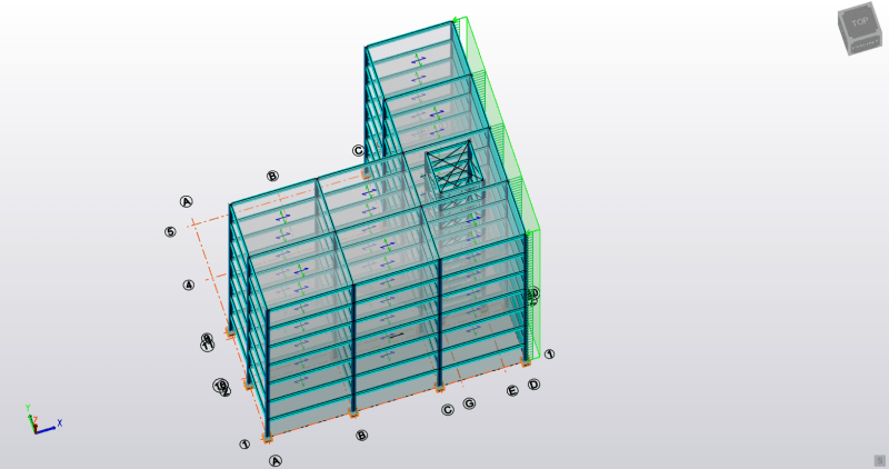
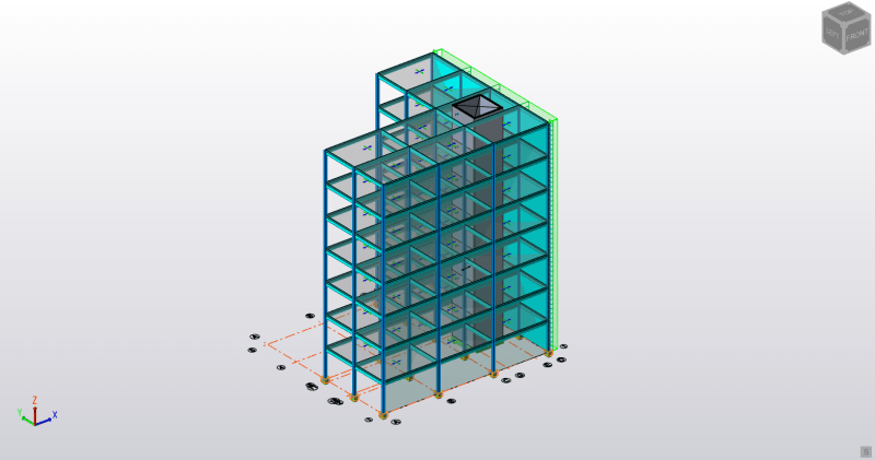
Here is the building I am working on:
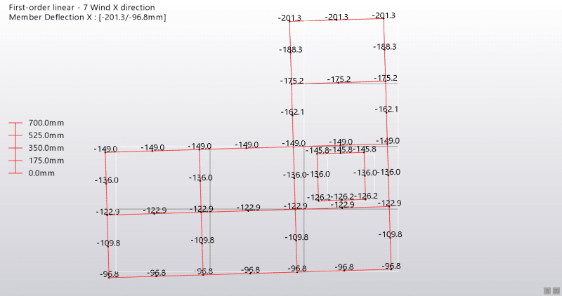
I start with calculating the shear stiffness of each sub frame that makes up the entire structure in the X and Y directions. Look at the following plan of my building:
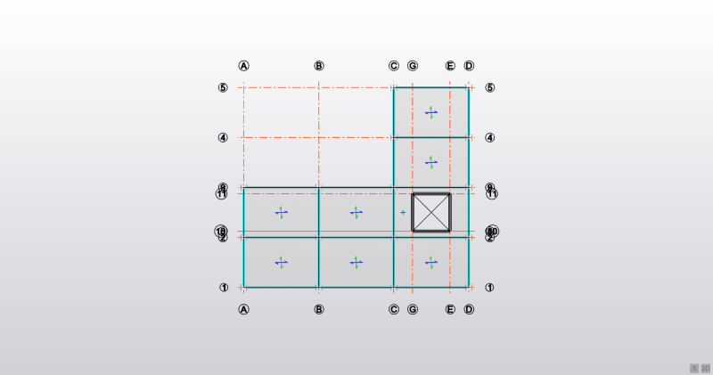
The X direction is from left to right, the Y direction is from top to bottom, with the wind pressure acting on the structure from right to left.
I hope you can see the frames in the X direction (parallel to the wind load) are made up of 5 frames. Going from bottom to top in the plan we have 3 frames that have 4 columns and 3 beams; then there are 2 more frames that have 2 columns and 1 beam.
To compute the shear stiffness of a frame we can use the formula:
[/indent][pre]Kframe1 = Kb*(Kc/(Kb + Kc))
where:
Kc = sum (12*E*Ic)/h^2
Kb = sum (12*E*Ib)/(h*l)
E = modulus of elasticity of the steel
Ic = second moment area of the columns
Ib = second moment of areas of the beams
h = storey height
l = bay width[pre][/pre]
Thus, for the first frame in the X direction, we would get:
[pre]Kc = 4*12*E*Ic/h^2
Kb = 3*12*E*Ib/(h*l)[/pre]
This procedure is reapeated for all the frames in the Y direction.
So we have the shear stiffness of 5 frames in the X direction and 4 frames in the Y direction.
Lets call these frames:
[pre]K1x
K2x
K3x
K4x
K5x
K1y
K2y
K3y
K4y[/pre]
Now, a coordinate system must be defined. Taking the bottom left corner as the origin, we find the centroids of all the frames. This is easy as its just the centre of each frame. Hence in the Y direction:
[pre]K1x = 0m
K2x = 4m
K3x = 8m
K4x = 12m
K5x = 16m[/pre]
And in the X direction:
[pre]K1y = 0m
K2y = 6m
K3y = 12m
K4y = 18m[/pre]
From this I can calculate the centre of stiffness
[pre]ybar = (K1x*0 + K2x*4 + K3x*8 + K4x*12 + K5x*16)/(K1x + K2x + K3x + K4x)
xbar = (K1y*0 + K2y*6 + K3y*12 + K4y*18)/(K1y + K2y + K3y + K4y)[/pre]
For my building, these coordinates are:
[pre]ybar = 6m
xbar = 10.67m[/pre]
Now the torsional stiffness is required. For this a new cooordinate system must be defined, where the origin is the centre of stiffness. Thus:
[pre]t1x = ybar - 0
t2x = ybar - 4m
t3x = 8m - ybar
t4x = 12m - ybar
t5x = 16m - ybar
t1y = xbar - 0
t2y = xbar - 6
t3y = 12m - xbar
t4y = 18m - xbar[/pre]
The torsional stiffness is obtained by:
[pre]q1x = K1x*t1x^2
q2x = K2x*t2x^2
q3x = K3x*t3x^2
q4x = K4x*t4x^2
q5x = K5x*t5x^2
q1y = K1y*t1y^2
q2y = K2y*t2y^2
q3y = K3y*t3y^2
q4y = K4y*t4y^2
qw = (q1x + q2x + q3x + q4x + q5x + q1t + q2y + q3y + q4y)
[/pre]
The total force coming from the wind is:
Fwind = 10 kN/m^2*H*B
Where:
[pre]H = height of the building
B = width of the building face that the wind is acting upon[/pre]
The moment induced is simply:
[pre]Mwind = Fwind*(8 - ybar)[/pre]
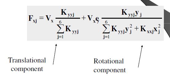
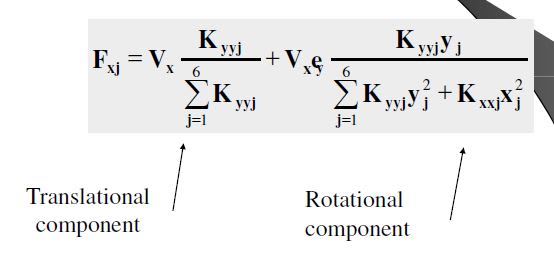
Now the load share of frame1 can be computed by:
[pre]F1 = Fwind*(K1x/(K1x + K2x + K3x + K4x) - Mwind*(K1x*t1x/qw)[/pre]
For the other frames use their stiffnesses and plug them into the above equation.
Sorry for this post being so long, but I thought it was a good idea to show you what I am doing. Again, I need to find out how stiff a concrete core is. I have the modulus of elasticity and second moment of area for it, but the equations I have tried like: [pre](8*E*I)/H^4[/pre] are not working!
Many thanks in advance,
Tygra
I have been working on a problem in which I would like to calculate the load shares and deflections of structural elements in a multi-storey building. These elements include moment-resisting rigid frames, diagonally braced frames, concrete cores, and shear walls.
Thus far, I have achieved very good approximations for irregularly shaped buildings that contain just moment-resisting rigid frames. However, now I am trying to do the same but with the addition of concrete cores. I need to know the stiffness of the concrete core so that I can include it in my calculations for stiffness of the entire structure?? This is going to be a long post, so if you can answer my question you can stop here. If you are interested in the procedure read on.
Because my building is asymmetric it will experience a torsion and a translation
Here is the building I am working on:

I start with calculating the shear stiffness of each sub frame that makes up the entire structure in the X and Y directions. Look at the following plan of my building:

The X direction is from left to right, the Y direction is from top to bottom, with the wind pressure acting on the structure from right to left.
I hope you can see the frames in the X direction (parallel to the wind load) are made up of 5 frames. Going from bottom to top in the plan we have 3 frames that have 4 columns and 3 beams; then there are 2 more frames that have 2 columns and 1 beam.
To compute the shear stiffness of a frame we can use the formula:
[/indent][pre]Kframe1 = Kb*(Kc/(Kb + Kc))
where:
Kc = sum (12*E*Ic)/h^2
Kb = sum (12*E*Ib)/(h*l)
E = modulus of elasticity of the steel
Ic = second moment area of the columns
Ib = second moment of areas of the beams
h = storey height
l = bay width[pre][/pre]
Thus, for the first frame in the X direction, we would get:
[pre]Kc = 4*12*E*Ic/h^2
Kb = 3*12*E*Ib/(h*l)[/pre]
This procedure is reapeated for all the frames in the Y direction.
So we have the shear stiffness of 5 frames in the X direction and 4 frames in the Y direction.
Lets call these frames:
[pre]K1x
K2x
K3x
K4x
K5x
K1y
K2y
K3y
K4y[/pre]
Now, a coordinate system must be defined. Taking the bottom left corner as the origin, we find the centroids of all the frames. This is easy as its just the centre of each frame. Hence in the Y direction:
[pre]K1x = 0m
K2x = 4m
K3x = 8m
K4x = 12m
K5x = 16m[/pre]
And in the X direction:
[pre]K1y = 0m
K2y = 6m
K3y = 12m
K4y = 18m[/pre]
From this I can calculate the centre of stiffness
[pre]ybar = (K1x*0 + K2x*4 + K3x*8 + K4x*12 + K5x*16)/(K1x + K2x + K3x + K4x)
xbar = (K1y*0 + K2y*6 + K3y*12 + K4y*18)/(K1y + K2y + K3y + K4y)[/pre]
For my building, these coordinates are:
[pre]ybar = 6m
xbar = 10.67m[/pre]
Now the torsional stiffness is required. For this a new cooordinate system must be defined, where the origin is the centre of stiffness. Thus:
[pre]t1x = ybar - 0
t2x = ybar - 4m
t3x = 8m - ybar
t4x = 12m - ybar
t5x = 16m - ybar
t1y = xbar - 0
t2y = xbar - 6
t3y = 12m - xbar
t4y = 18m - xbar[/pre]
The torsional stiffness is obtained by:
[pre]q1x = K1x*t1x^2
q2x = K2x*t2x^2
q3x = K3x*t3x^2
q4x = K4x*t4x^2
q5x = K5x*t5x^2
q1y = K1y*t1y^2
q2y = K2y*t2y^2
q3y = K3y*t3y^2
q4y = K4y*t4y^2
qw = (q1x + q2x + q3x + q4x + q5x + q1t + q2y + q3y + q4y)
[/pre]
The total force coming from the wind is:
Fwind = 10 kN/m^2*H*B
Where:
[pre]H = height of the building
B = width of the building face that the wind is acting upon[/pre]
The moment induced is simply:
[pre]Mwind = Fwind*(8 - ybar)[/pre]
Now the load share of frame1 can be computed by:
[pre]F1 = Fwind*(K1x/(K1x + K2x + K3x + K4x) - Mwind*(K1x*t1x/qw)[/pre]
For the other frames use their stiffnesses and plug them into the above equation.
Sorry for this post being so long, but I thought it was a good idea to show you what I am doing. Again, I need to find out how stiff a concrete core is. I have the modulus of elasticity and second moment of area for it, but the equations I have tried like: [pre](8*E*I)/H^4[/pre] are not working!
Many thanks in advance,
Tygra

