Continue to Site

Eng-Tips is the largest engineering community on the Internet

Intelligent Work Forums for Engineering Professionals

  • Congratulations KootK on being selected by the Eng-Tips community for having the most helpful posts in the forums last week. Way to Go!

STM - Wall on wall detail 1

Status
Not open for further replies.

hardbutmild

Structural
Aug 10, 2019
294
Hello everyone,

I have a question about STM and would like to hear your opinions.
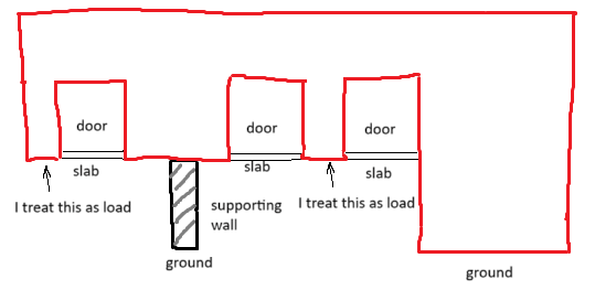
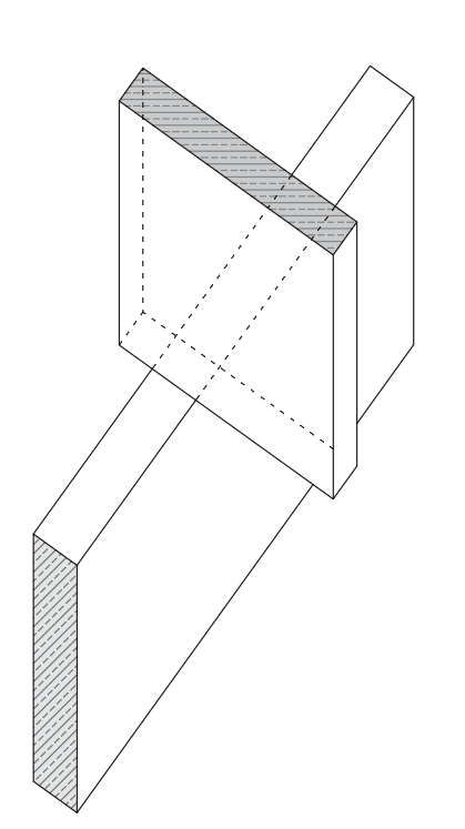
I have two perpendicular walls, one sitting on top of another (so the top wall is some sort of deep beam supported on an orthogonal wall). This is a quick sketch of the problem:
picture_1_bylwad.png

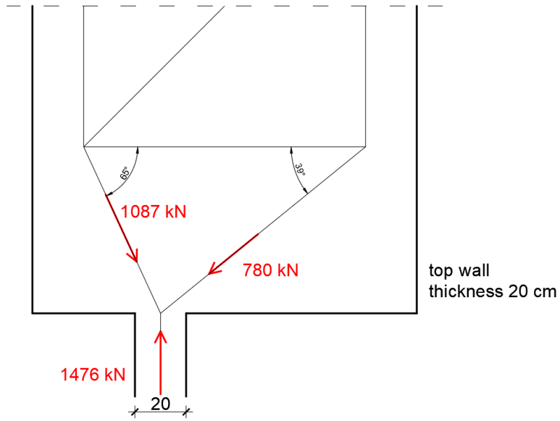
Both of the walls are 20 cm thick so their contact is relatively small. I made an STM model of the whole top wall (it has 2 supporting walls, this is a detail of one of them) and this is just a part of that model -a detail of the connection:
picture_2_nth2w9.png

Now, of course, I know that it is better to divide the support force into two, one for each diagonal, but that is not important here. I also know that the left diagonal will probably fail here, but these are all things that I can find a solution to.
My problem is the contact point of the two walls, so the transfer of 1476 kN. What is the allowable pressure in your opinion? If I divide the force by area I get 36,9 MPa (1476000 / 200*200) - this is more than the design strength of 20 MPa.
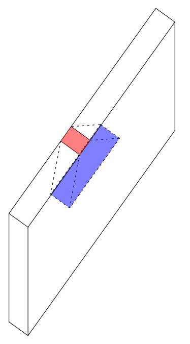
The question is does this need to be satisfied or can this stress be distributed to a larger area of the supporting member like in this picutre:
picture_3_lrhxdt.png

Eurocode has provisions for "partially loaded areas" where the strength increases by 2-3 times. This would help significantly in situations like these.

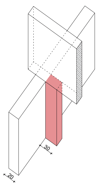
I know that I can always do something like the following picture to reduce the stress and it's certainly a better solution, but is it strictly necessary?
novo_mvc2le.png
 
Replies continue below

Recommended for you

I know nothing of Eurocodes. In ACI, we have a capacity for bearing pressure. That's what I'd be looking at.
 
Thanks Pham, that helps... I'll look up ACI. Is this capacity usually larger or smaller than fc'?
 
Usually smaller in my experience. In Canada, which matches pretty close with the ACI code, it's 0.85*0.65*fc' roughly. meaning there's a fairly large reduction compared to strictly the strength of concrete.
 
Less than, though you can get a boost if the surface is larger than the bearing area. Your pilaster is probably going to be necessary.
 
I don't love an old fashioned bearing check for this. I feel that it lacks the sophistication required to properly capture the important aspects of the problem. Such a check has three limitations that I feel are important for this situation:

1) Simplified bearing assumes that the compression field is symmetrical coming off of the contact patch. That is often not the case for situations like these where the struts race off diagonally which tends to increase the axial stress in the struts.

2) Simplified bearing assumes confinement of the node which, often, will not be the case for a node with a rebar tension tie running through it. So lower compression stresses are appropriate.

3) A bearing check does little to address the most important consideration at the joint: tie anchorage. Presumably, you're still looking at tie anchorage separately.

hardbutmild said:
Eurocode has provisions for "partially loaded areas" where the strength increases by 2-3 times. This would help significantly in situations like these.

I've no doubt that you're asking this question precisely because that sounds a bit too good to be true. And your instincts are correct, it is in fact too good to be true.


Thanks everyone. I guess we have a consensus - allowable stresses can not be increased, pilaster is necessary.

@KootK What do you think should be checked instead of bearing stress?
I usually do not connect the struts in one point, but divide the bearing in two, one for each diagonal (if that is what you meant by 1)
As for 2) and 3), they are not really an issue here... this is a CCC node. Of course, if there is a tie the whole discussion changes drastically.

I'm mostly confused as to what is the increase given in the code intended for - even for precast beam on column (where the support is larger in both horizontal dimensions) usually stresses are limited to something like 40 % of the strength.

There is also another question with this situation - would placing closed horizontal ties in both walls help increase the allowable pressure?
 
OP said:
@KootK What do you think should be checked instead of bearing stress?

Full on STM which will include a more strenuous version of a bearing check at the node.

OP said:
this is a CCC node. Of course, if there is a tie the whole discussion changes drastically.

Yeah... that. I feel that this is actually a CCT node. Or ought to be. That said, find your STM modeling choice surprising. Can we see the model of the whole thing in its entirety?

OP said:
I'm mostly confused as to what is the increase given in the code intended for - even for precast beam on column (where the support is larger in both horizontal dimensions) usually stresses are limited to something like 40 % of the strength.

The increase accounts for the benefit provided by confinement in a particular kind of bearing joint (see the limitations discussed in my previous post). The simplified -- and favorable -- version of the bearing check is really a subset of the more general STM checks. In my opinion, if a full on STM bearing check fails, the simplified check should not be taken as superseding that result.

OP said:
There is also another question with this situation - would placing closed horizontal ties in both walls help increase the allowable pressure?

Probably. And lost of folks do this, similar to walked column transition zones. That said, it too creates the danger of optimism. This undoubtedly improves confinement at the bearing interface but still ought to be woven into a complete story that is consistent with the other things going on in the vicinity of that interface.

 
OP said:
I divide the force by area I get 36,9 MPa (1476000 / 200*200)

Too high. Also, you will in reality have a triangular stress distribution, or worse, meaning the edge will see much higher localised stresses than your hypothetical rectangular distribution. Add some cast-in steel bearing plates, to armour this weak point.
 
KootK said:
Full on STM which will include a more strenuous version of a bearing check at the node.
Do you mean that the check is something different than force/area or simply that the limits will be different?

KootK said:
Yeah... that. I feel that this is actually a CCT node. Or ought to be. That said, find your STM modeling choice surprising. Can we see the model of the whole thing in its entirety?
I can put up the whole model tomorrow, it's quite a late hour where I'm at. I still don't have a final version with all the checks, since I want to define the geometry first (now I know I'll add a pilaster that should easily pass the check), but I do have all the elements of a truss. At least I think I do, you're making me think now. The top wall is similar to a greek letter PI. This is the bottom of the left leg of letter PI where it is supported on the orthogonal wall. The other, right leg is supported on the ground directly along the whole length.
 
OP said:
Do you mean that the check is something different than force/area or simply that the limits will be different?

Different limits. And perhaps parts of the node other than the bearing interface being the limiting factor.
 
OP said:
The top wall is similar to a greek letter PI.

Huh, I did not see that coming. Perhaps my comments were premature then, we'll see.
 
Untitled_gjkpqs.png


It looks something like this (there's a slab on top as well). I know it's a mess. Now you made me think that maybe slab will act as a tie even if I make a model not relying on that tie action... hmm
Sure, I know that the top part of the node can be the limiting factor, but that is a different problem - I know that the limit for that can not be increased, I was wondering for the bottom part. That is why I asked only for the point of connection.
 
Haven't read all of this, but be careful using the increase for sqrt (A1/A2) as you don't have confinement in both directions.
 
Don't know about other codes/juristiction but in Aus standards ordinary bearing calcs are not applicable to an S&T configuration. There's separate equations for calculating the allowable stresses at each face of a node, and you don't get any ability to increase the allowable stress from that sort of expanding cone shape thing (no idea what the way to call it is, but it's doing the sqrt(Area2/Area1) calc).

----------------------------------------------------------------------

Why yes, I do in fact have no idea what I'm talking about
 

hardbutmild said:
I just screened the previous posts . Apparently there are other limiting factors acc. to the last sketch you have posted.One of them is the stability of the walls .
Is this a structure with parallel wall system ( tunnel formwork )?
My suggestion as a first step , would be add pillars at both sides so the bearing area would be (200X600 mm ) and suggest you to look (. h. Fritz Leonhardt, Dipl.-Ing. Eduard Mönnig (auth.) - Vorlesungen über Massivbau_ Zweiter Teil Sonderfälle der Bemessung im Stahlbetonbau)
It is hard ( at least for me ) to visualize your case clearly. Can you post some extra details ( storey plans etc)

..

He is like a man building a house, who dug deep and laid the foundation on the rock. And when the flood arose, the stream beat vehemently against that house, and could not shake it, for it was founded on the rock..

Luke 6:48
 
Thank you everyone. I will deffinitely go with the pilaster.

@slickdeals - This also crossed my mind - when I confine a column it needs to have stirrups in both directions for confining to be effective, why would I allow confinement here if it is only in one direction.

@JustSomeNerd It makes sense.

@HTURKAK Sure, there are other limiting factors. The thing is that I know how to check them and what I can count on. I was unsure about the bearing pressure. It is not a tunnel formwork. I am aware of Leonhardt, but it is hard to follow because I don't speak german.

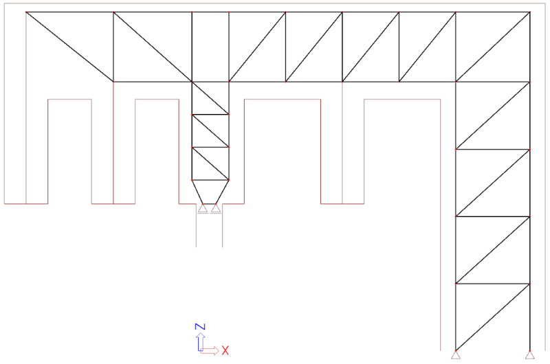
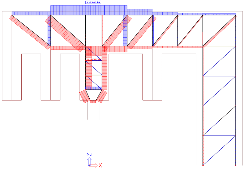
Here is my STM truss and forces with supports in the top picture and internal forces in the bottom picture (brown lines show the outline of the wall and the center of a hanging block. Blue is tension, red is compression. Unfortunately when the force is 0 in an element it is also a type of blue. Just to be clear: no diagonals are in tension! Of course, only axial forces exist and I tried changing many elements dimensions - internal forces do not change. There are also no horizontal reactions. I believe that the left support area is a CCC node, it sure looks like it to me.

1_iiobls.png

2_nrlqdk.png
 
OP said:
Now you made me think that maybe slab will act as a tie even if I make a model not relying on that tie action... hmm

Yeah, the slab could potentially act as a compression strut. Which, still, is not a CCT node. As such, I rescind my previous concerns. This would actually be a pretty robust application of the simplified bearing checks suggested by our fine colleagues above. My bad.

While you could use the slab as a compression strut, I like the model just the way that you have it. Beam over column, nice and simple. If you get some incidental vierendeel action the system that reduces deflections etc, so much the better.

I think that a lot of folks would be willing to simplify the design of the column element even further by considering it a strip of wall will concentrated loads at either end. There are some nice, tidy code provisions for such situations. And we gots 'ta earn after all.
 
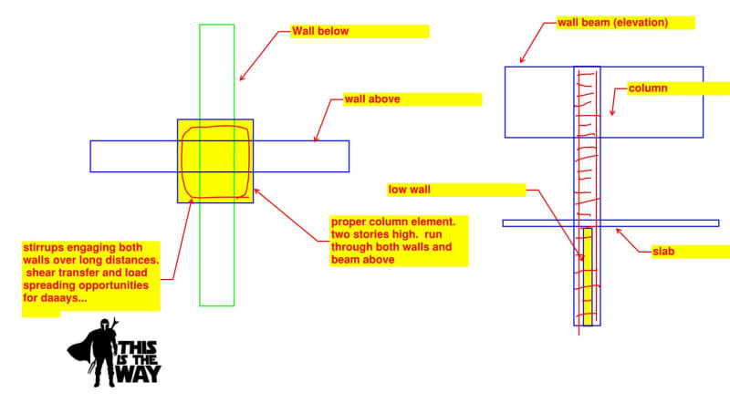
My cadillac solution for something like this is shown below. That said, I fully appreciate that this is an option that you've probably already considered and have been forced to reject as a result of architectural constraints.

None of us relishes pussy footing our way around high demand bearing situations.

c01_x2a7jo.jpg
 
I would be remiss if I didn't mention that my cadillac solution is also kind of a formwork nightmare. So one would have to be prepared to defend that. Sometimes hard things are just... hard things. Not every compromise should be the engineer's to make.
 
Status
Not open for further replies.

Part and Inventory Search

Sponsor