Eng-Tips is the largest engineering community on the Internet

Intelligent Work Forums for Engineering Professionals

  • Congratulations waross on being selected by the Tek-Tips community for having the most helpful posts in the forums last week. Way to Go!

Strange "Flat Solid" of Conical Sheet Metal Piece...

Status
Not open for further replies.

DBlair126

Mechanical
Jun 3, 2019
2
0
0
US
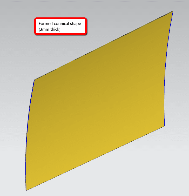
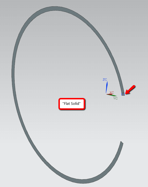
I have several conical pieces of sheet metal (created in Modeling, then Converted to Sheet Metal) which either do not successfully calculate when doing a Flat Pattern or if they do, it creates a strange flat loop...

Anyone have an idea of what may be going on? I've done the "clean up" tool and the behavior is the same. Thanks for the help!

Here's what it's looking like...
2019-06-03_0958_qejbco.png

2019-06-03_0957_jnds24.png
 
Replies continue below

Recommended for you

Sheet Metal application is not suitable for conical or rolled parts - it's mainly for bent parts - bends along a straight line. You can also work with punch features in Sheet Metal, but punch features are not considered for flattening.
You can create a sheet metal part in modeling and convert. And also flatten it, when certain rules are followed. Mainly plain and cylindric geometry is considered only.
When you convert and you get the alert that some geometry can not be unbend, then it is so. Flattener can only flatten the "rest" then.
Rolled parts can be in some cases simulated with the Lofted Flange. The cone (between two arcs) is realized with several smaller bends. I don't know how your part is really looking like, but if the right and the left edge are arcs and the upper and lower edge are straight lines, maybe it's worth to try the Lofted Flange.
But back to the original "Flat Solid": That looks really funny :)

Flattener outside Sheet Metal you can try:
[ul]
[li]Analyze Formability[/li]
[li]Flattening and Forming (in Edig/Surface)[/li]
[/ul]
 
I would be interested to see the input prt file for that result. May I suggest you raise an IR with GTAC and submit the file for analysis.
 
Thanks everyone. Lofted flange didn't quite replicate the geometry, but I did find another work around I'll share in case someone runs across this thread with a similar situation:

1. In Modeling, "Extract Geometry" and selected the inner Face
2. "Thicken", selected the extracted face and entered the sheet metal thickness I want, OK
3. "Remove Parameters" and select both the Thicken solid and the Extracted Face in the Model History tab
4. Deleted all solids except for the de-parameterized solid that was created with "Thicken"
5. In Sheet Metal, "Convert to Sheet Metal" and select the inner face of the new solid, OK
6. Then select the same inner face and "Flat Solid" and "Flat Pattern" work perfectly!

There's probably a more efficient way to do this but this works for now. My theory is that the edge faces of the original sheet metal body were not perpendicular to the "base" face so the code couldn't figure out where to stop flattening...

[thumbsup2]
 
Status
Not open for further replies.
Back
Top