Eng-Tips is the largest engineering community on the Internet

Intelligent Work Forums for Engineering Professionals

  • Congratulations waross on being selected by the Tek-Tips community for having the most helpful posts in the forums last week. Way to Go!

STRAP FOOTING

Status
Not open for further replies.

gotlboys

Civil/Environmental
May 31, 2015
61
0
0
TL
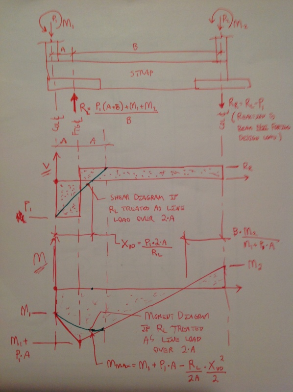
I am designing a corner footing supporting a three-storey steel building. Steel columns are supported by concrete pedestals. Three pedestals sit on the property line which calls for 'strap footing' as a solution. I have some references that deal with such footing but they don't have one which involves moments (DL, LL, ME).
It will really be helpful if anyone can share with me a manual solution.

Thanks a lot for any help.
 
Replies continue below

Recommended for you

A strap footing is just a grade beam which cantilevers over a footing which is set back from the property line, to pick up a column which is at the property line. The backspan of the grade beam continues on to an interior footing.

DaveAtkins
 
gotlboys said:
I have some references that deal with such footing but they don't have one which involves moments (DL, LL, ME).

I've not seen an example of this in print either. I would:

1) Add the column moments and shears to the grade beam and track the loads through and;

2) Give some consideration to the rotational restraint that the strap beam will or won't provide to the column as that will impact drift and first story stiffness.

I like to debate structural engineering theory -- a lot. If I challenge you on something, know that I'm doing so because I respect your opinion enough to either change it or adopt it.
 
EireChch, I have uploaded a photo of the foundation plan.

Yes, the strap acts as cantilever beam to transfer some loads to the interior column.
If there have been axial loads only, it would have been easy to draw the S&M diagrams.
Calculated loads are P(ext) = 239kN, P(int) = 444kN, M(ext)=51kNm, M(int)=103kNm.

Please show me a solution at your convenience.
 
 http://files.engineering.com/getfile.aspx?folder=ed75e397-e586-4407-a001-930dc7f710a7&file=strap_footing.jpg
So your moment frames run in the East to West direction then, with weak axis columns? If so,

1) Add your two moments together for the direction considered.

2) Divide the sum by the distance between footing centroids to get the additional overturning reactions, associated footing bearing pressures, and associated uniform loads exerted by the footings on the strap beamfor this component of the load.

3) Create moment and shear diagrams for the strap including the effects of the concentrated column moments and the uniform footing loads from #3.

4) Add the moments and shears from #3 to the moments and shears that you would have had without the moments applied.

Can you provide:

1) distance between columns?
2) distance between footing centroids?
3) direction of frame shear for case considered?
4) depth of strap beam?

The column shears technically affect strap moments, shears, and axial forces too but that affect should be fairly minor.

I like to debate structural engineering theory -- a lot. If I challenge you on something, know that I'm doing so because I respect your opinion enough to either change it or adopt it.
 
Do you still need help with this gotlboys? Sorry for the late response. I was out of town for a spell.

I like to debate structural engineering theory -- a lot. If I challenge you on something, know that I'm doing so because I respect your opinion enough to either change it or adopt it.
 
IMG_0348_ulpabw.jpg


I like to debate structural engineering theory -- a lot. If I challenge you on something, know that I'm doing so because I respect your opinion enough to either change it or adopt it.
 
P2 isn't included because it is assumed to go right into the footing below it and not into the beam. It isn't the moment or shear that need to be zero at the left end, it's the reaction,

I like to debate structural engineering theory -- a lot. If I challenge you on something, know that I'm doing so because I respect your opinion enough to either change it or adopt it.
 
I was referring to shear & moment diagrams. They don't end at zero as shown in the spreadsheet. Even so we can still get the maximum moment and shear to design the strap beam.

Now, I am bit confused on how to transfer some load to F2 (int) since P2 isn't included?
How do I determine the dimension of F2 and the forces to determine reinforcements?
 
Neither the moment nor the shear should be zero at the ends. The sketches below show it set out algebraically. Do a similar analysis with the moments reversed and P1 at its minimum to get your design load for F2.

IMG_0350_llrr1h.jpg


I like to debate structural engineering theory -- a lot. If I challenge you on something, know that I'm doing so because I respect your opinion enough to either change it or adopt it.
 
Kootk, thank you so much for taking some time to do it in detail.

Will F1 be provided with top steel parallel to the strap? or the negative moment is all carried by the strap beam and thus F1 doesn't have to carry any negative moment.
 
You're most welcome gotlboys.

OP said:
or the negative moment is all carried by the strap beam and thus F1 doesn't have to carry any negative moment.

This exactly. That is, of course, unless you're countie on tie down force from the footing when the moments are reversed.

I like to debate structural engineering theory -- a lot. If I challenge you on something, know that I'm doing so because I respect your opinion enough to either change it or adopt it.
 
Status
Not open for further replies.
Back
Top