Continue to Site

Eng-Tips is the largest engineering community on the Internet

Intelligent Work Forums for Engineering Professionals

  • Congratulations KootK on being selected by the Eng-Tips community for having the most helpful posts in the forums last week. Way to Go!

Strengthening Cover Plate - Detailing? 2

Status
Not open for further replies.

psychedomination

Structural
Jan 21, 2016
114
Hi there,

I'm working on a project where the client is trying to put a heavy piece of equipment on a roof. I ran a model and found that the beams the equipment will be resting on would be overstressed (~15%) and fail in bending (sagging only).

To strengthen the beam, I was looking to bolt a partial length cover plate to the bottom of the existing beam flange. I haven't done this type of strengthening before. In theory this seems quite simple, the additional section increases the section modulus, which then increases the moment capacity. However, when it comes to the detailing best practice, I can't find much guidance on this?

A few questions I have is :

1. What is the minimum spacing of bolts to take the shear flow. When I carried out the calculation, to take the shear flow the bolts only needed to be spaced 12" apart. However, I read online here : that the bolts should not be spaced more than the flange width apart. I went with this approach conservatively but I was wondering if this is general practice?

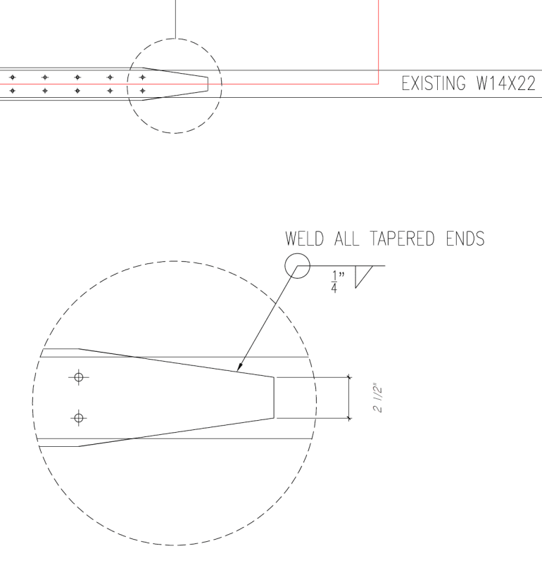
2. The cover plate is partial length (total length of beam is 25' but the cover plate only needs to be ~12' based on the applied moments). I have the end taper as 1' long (tapering from 6" to 2.5") with a fillet welded all around the tapered portion. Is there any guidance on sizing the end detail that someone can provide?

3. Am I missing anything here or is there anything I should be concerned about when considering construction? I oversized the width of the new plate slightly, allowing a 1/2" overhang on each end to allow the contractor to carry out a top down tack weld if they wanted to keep it in place when bolting. I'm not sure what other considerations I should include to ease construction?

Details I was thinking of using are below :
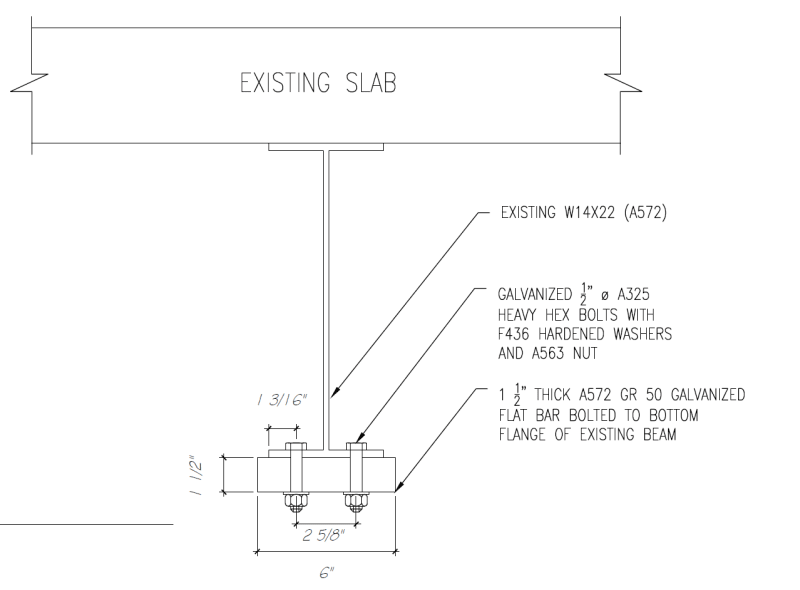
Detail_1_-_Copy_bgjm3w.png
Detail_2_-_Copy_e3fg0s.png


Any assistance/advice or guidance would be appreciated.
 
Replies continue below

Recommended for you

I haven't done this type of strengthening before. In theory this seems quite simple...
Any assistance/advice or guidance would be appreciated.
Theory is simple, but putting it into practice is another matter.

Start over. Read (carefully) the logical step-by-steps needed to do this right "Steel Beam Reinforcement"

A 15% increase in moment capacity is not going to take much (thickness) of a cover plate. I have not done the calcs, but an 1 1/2" thick plate is way oversized... which adds unnecessary dead load, increases construction difficulty, and makes more drastic change in the composite beam's moment capacity at the transition points. Besides, a W14x22 is not exactly a robust beam, 1/4" thick web and 5/16" thick flanges. A cover plate more like 5/16" + thick is probably going to be plenty.

Section modulus of a composite beam cannot be calculated directly, use the parallel axis theorem (from statics) to find the composite's moment of inertia, then calculate section modulus

Don't use galvanized plate; welding to galvanized steel is not something a welder chooses to do... for good reason.

Bolts should be slip critical. Your proposal to make the cover plate wider than the beam flange is good; consider taking advantage of this down-hand welding opportunity instead of bolts.

When installing the cover plate, use jacks to take off as much existing load from the beam as practical... this will decrease the existing beam's deflection when the cover plate is being put on.

 
And better check web buckling directly under the new equipment. That web looks thin.
 
@SlideRuleEra,

Thanks, the document you linked is extremely helpful!

The client was mainly looking for drawings to go out for pricing and they didn't provide me with confirmed weights (contractor was going to choose a supplier etc), so I was a bit conservative with the reinforcing (although perhaps too conservative), with the assumption that the loads would end up being slightly higher. I'll run through the document you sent and see if I can get a thinner plate to work.

As for the galvanized plate, this is an interesting one. I'm in a very humid/corrosive location (similar to Florida) and the steel tends to corrode quite rapidly here. However, to counter this issue, as it seems to be troublesome to weld galvanized steel, perhaps I can have the contractor use the standard carbon steel and then coat it with a zinc rich primer and top coat after plate is in place? Only thing is it would most likely corrode on route to the site, so would need to have suitable surface prep after this before applying the coating.

Any particular reason why the bolts need to be slip critical? I thought that they would just need to take the shear flow, which I would've thought could be done with standard bearing bolts?

Initially I was considering just welding the plate but thought it may be more expensive. However, if slip critical connections are required welding may end up being similar price or cheaper when considering the surface preparation requirements for slip critical connections.

Thanks for the tip about using jacks to reduce the load/deflections. I don't see it being an issue to use jacks on either side of the beam to reduce the existing load. I can put a note in the drawings to this effect.

Very helpful advice so far thanks!

@SWComposites, that is a good point. I'll check that as well. Thanks!

 
The link I gave you will answer several of your current questions, including welding vs. bolting.

We have chatted before, I know you are in a humid climate... so am I, the South Carolina coastal plain. Don't galvanize the plate, use high quality coatings (i.e. "paint").

If bolts are used slip critical is essential. The beam bottom flange and and cover plate MUST move (precisely) together as deflection tends to occur; the least slip... there goes the advantage of having a cover plate.
Also think about this: If you use bolts and cover plate becomes essentially "structurally worthless" because of slippage, most of the tensile force must be resisted by the W14's bottom flange... which you have turned into "Swiss cheese" with numerous bolt holes in the part of the beam with highest bending moment.

For any welding, make sure the A572 beam and plate have similar welding requirements. They need to be welded together, for example, A572 and A36 steel can be welded together.

Use a thinner plate, but not necessarily the the calculated thinnest. Being from the "slide rule era", I can tell you with only "back of envelope" calcs that a 3/16" x 6" plate will provide well over 15% increase in moment capacity. But I would never use a cover plate that thin.

This brings up a question; you mention the existing beam "fails in bending (sagging only)".

Do you mean overstressed?
or​
Excessive deflection?

Depending on which problem there may be different solutions.

 
I find it odd that you are going to reinforce a 22 pound/foot beam with a plate which weighs 30 pounds/foot. You should find this odd as well.

I note that the beam is failing in "sagging only". What other type of flexure would there be in such a simple system?

If deflection is the issue then if will be difficult to estimate the effect when just the middle half of the beam is reinforced.

 
Thanks SlideRuleEra, the document did answer quite a few of my questions.

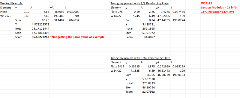
However, I ran through the worked example and I am running into one discrepency. When calculating the section properties on page 5, I am not getting the same section modulus for the compression flange, so I may be doing something wrong here.

The beam used in the worked example is a W12x26 beam, which would have an initial depth of 12.22 in. When adding a 3/8 thick plate, the overall depth d = 12.6 in.

The section modulus for the compression flange = I/d-Y
= 281.5/(12.6-4.88) =~ 36.5 in^3? The example is showing 41.9 in^3? Where am I going wrong here?

Calcs_r1_-_Copy_rd3xzr.png


That's a fair point regarding the slip critical connection.

I meant overstressed.
 
You might trying visiting the Lincoln Foundation website and look for a book by Omer Blodgett with the title Design of Welded Structures. There's a section on the design of cover plates.

Best regards - Al
 
A bit late to the party, but my two cents -
psychedomination I'm assuming that the equipment placement for your calcs is somewhere close to the beam center ?

If so, is there a possibility to flip this back to the suppliers and have them put the equipment on spreader beams such that the spreader supports are close to your beam supports ? Assuming the spatials work out and the suppliers agree, this could reduce moments significantly and may even help do away with the cover plate.
 
@gtaw, thanks I took a look at that book. It has some interesting information on the welding effects on beam deflections for this type of strengthening.

@FE struct1 Yes, the current assumption (based on discussions with a supplier) is that this HVAC equipment will need 8 vibration isolators , which would be located within stub columns (therefore 8 concentrated loads on the beam - 4 of which would be mid span). The supplier will be responsible for designing the equipment lifting frame/spreaders. However, the supplier for this project isn't confirmed yet, as this is a preliminary design going to various contractors/suppliers for preliminary pricing, so it is possible that we may end up only needing 4 vibration isolators/stub columns (depending on the supplier) and if that is the case then yes the supports can be over or near the columns. This would definitely be the cheaper option, that I'll look into when I get some confirmed information from the supplier.

 
psyche - Looks to me like you are not doing anything wrong. I worked the example problem, by hand, the classical way (Statics per Beer & Johnston, First Edition - 1962). Within round off error, I got the same answers you did:

I [sub]composite[/sub] = 281 in[sup]4[/sup]
S [sub]composite[/sub] = 36.3 in[sup]3[/sup] in the compression flange.

The author seems to take some "strange" steps and leaves out lot. I believe the example is wrong.

My calcs attached.

 
 https://files.engineering.com/getfile.aspx?folder=9062198a-ad73-4b64-a3ee-596a5f701231&file=Composite_Beam.pdf
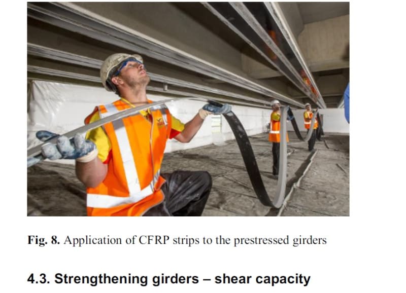
Just Add CFRP Strip with bonding epoxy [cheap - effective solution]
01_jpptyi.jpg
 

To develope that shear interface, it may take a real number of bolts. [pipe]

So strange to see the singularity approaching while the entire planet is rapidly turning into a hellscape. -John Coates

-Dik
 
psychedomination said:
I ran a model and found that the beams the equipment will be resting on would be overstressed (~15%) and fail in bending (sagging only).

What does this mean? - strength or serviceability issue?
 
@SlideRuleEra - Ok thanks, I was trying to figure out what was going on. Other than a few mistakes - the document you provided is very helpful and I've included it in my reference library.

I revisited the structural model for this project and the beams were overstressed (strength) by 12%. When considering this value, I got the 3/8" thick plate to work (barely). I'll use this with intermittent welds, instead of slip critical bolts.

I'll keep the plate as A572 50 ksi to keep the yield strength values the same between both structural elements.

The shear flow for this project is quite low. The minimum intermittent weld requirements from AWS govern. Ends up being 1/4" welds, 1.5" long at 8" centers (max spacing taken as 24*thickness of the thinnest section being joined).

I'll get the contractor to prop the slab on either side of the beam whilst welding works are taking place.

Thanks everyone!
 
No fatigue issues? [ponder]

So strange to see the singularity approaching while the entire planet is rapidly turning into a hellscape. -John Coates

-Dik
 
No fatigue issues?

I was just about to mention that. On bridge girders we typically use bolted cover plates to avoid the substantial reduction in the fatigue stress limit for continuous welds, and intermittent welds reduce the limit even further. It may or may not be an issue here, but definitely something to check. Mixing welds with bolts in the same connection is a really bad idea, even if it's bolted as slip critical.

Rod Smith, P.E., The artist formerly known as HotRod10
 
@Dik I didn't think there would be any fatigue issues as the HVAC equipment will have vibration isolators installed.
 
Your 3/8" PL sounds more reasonable for the conditions described.

I didn't see it addressed earlier but keep in mind you have to consider existing DL stress in the calculations. It is true you can shore the surrounding slab to relieve DL then install the cover plate but as a practical manner that is very difficult. I usually design considering existing DL, in the case of 12% overstress I would think this approach should be feasible.

You mentioned HVAC on vibration isolators. It would probably be worthwhile to do a quick check of the beams natural frequency.
 
Status
Not open for further replies.

Part and Inventory Search

Sponsor