Continue to Site

Eng-Tips is the largest engineering community on the Internet

Intelligent Work Forums for Engineering Professionals

  • Congratulations KootK on being selected by the Eng-Tips community for having the most helpful posts in the forums last week. Way to Go!

Strengthening of existing steel beam under load 1

Status
Not open for further replies.

isidor_

Civil/Environmental
Aug 30, 2022
14
I am controlling the capacity of some existing beams in a structure for new loads. The beams are welded I sections, ~13m long, simply supported and it looks as if they will need reinforcing.

Some restrictions, limitations and other info
New columns cannot be added to reduce the span length.
They are under load and the load cannot easily be reduced as there is activity.
Temporary offloading by jacking up the beams is possible but not easy as the beam/slab is the third story.
They are only accessible from below, so only the bottom flange, the web and the underside of the top flange.
(Some of) The beams are already deflecting about 50mm, which limits the strengthening procedures, for example a "perfectly straight" section cant be inserted into or attached to the curved beam I assume.
The strengthening cannot add too much depth below the bottom flange.
The beams are quite tall and slender, 600-800mm tall with flanges about 350mm with a thin web.
The beams are primary beams, secondary beams are connected to them and brace them laterally at a few points reducing their buckling lengths.
Located in the EU if it makes a difference

I have searched and found some relevant threads but have a few questions.
Strengthening methods:
1. Welding of cover plates, I was thinking about adding a plate below the bottom flange, the plate being wider than the flange to get good (easier) welding from above. The plate could also be fitted in accordance with the curvature.
Since it is under load, any welding will cause the section to soften due to the heat which I assume adds deflection. How much of an issue is this?​
Since it is under load the bottom flange is already under tension stresses, while the new material should have (close to) no stresses, will this discrepancy cause issues?​
If the cover plate is welded without (partially) unloading the beam, then the added material will only effect additional loads?​
2. FRP reinforcement.
While I (personally) cannot do this, I could recommend it to the customer if it is feasible, is this a viable solution to recommend? It adds no heat, is lighter/easier to handle than additional (heavy) steel profiles, seems less of a project than welding aswell​
3. Post tensioning of the steel beam
I have (briefly) read some texts about this and it seems good. If done properly it seems to me that i could even remove some of the deformations on the beam. For instance adding a kingpost type of solution​
How is the connection properly done to the beam? Welding something to the thin web seems hazardous​
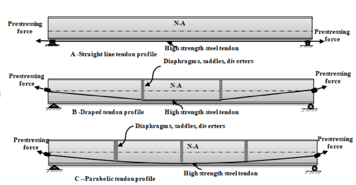
Regarding the detailing, the image below shows three examples.
The first one should be easiest to do since it would only attach to the bottom flange. But since the bottom flange is bent downwards wouldn't the prestressing cause it to bend further down? (I know it is below the NA so it gives a negative moment that should cause the beam to bend upwards, but part of my brain worries I am missing something...​
The second is the option I prefer, aside from the web connection at the ends ofc. The stiffeners where the tendon changes direction takes a compressive force upwards from the node causing the beam to elevate.​
Welding will be required here but will be more localized at the "nodes" so that is an positive at least​
Screenshot_2_srtq1v.png


Thanks in advance and hope my English is sufficient to convey the questions.
Any input into the matter is appreciated.
 
Replies continue below

Recommended for you

Not a structural engineer, so FWIW
1> isn't the vertical height of the entire beam that provides the stiffness, not the flange?

3> how much uplift force can you generate from the tension applied, wouldn't you more likely break the cable before any appreciable stiffening will occur?

I would think that doing what you might do with a wood beam, which is, in effect, to sister it with another beam and share the load might make more sense.

TTFN (ta ta for now)
I can do absolutely anything. I'm an expert! faq731-376 forum1529 Entire Forum list
 
I can't speak to trying to push a steel beam back up because I've never heard of anyone doing anything that wild, but my favorite reinforcing techniques for wide flange beams are rebar in the corners of the webs. Rebar is cheap and even using large diameter bars they can accommodate existing deflection.

I have also used solid square bars and/or angles in the corners of the webs if needed.

Often I'll combine rebar in the top 2 corners and a bottom flange plate. If the reinforcing needs to be really heavy I'll add WT's or even an additional wide flange beam underneath the existing beam while trying to avoid overhead welds were possible. But I can understand that these might be a bit more challenging if there is already a lot of deflection in the existing beams.
 
This is a tough challenge, I wouldn't hesitate to look for outside assistance can't come to a workable solution quickly. However you are asking the right questions which is a good start and better than many others posting here! [3eyes]

As you have already recognised strengthening something that is already under significant load that cannot be removed becomes quite problematic. You pretty much need to relieve some or all of that load to suitably engage the additional strengthening.

isidor_ said:
Since it is under load the bottom flange is already under tension stresses, while the new material should have (close to) no stresses, will this discrepancy cause issues?
Absolutely. The existing stresses are "locked in" unless you relieve the load by supports. Thus you need to either relieve the load OR provide significantly EXTRA strengthening reinforcement.
(Alternatively you are accepting significant yielding in the existing beam until load redistribution takes place. By doing so you are going to get some increase deflections and opening up multiple cans of worms.)

isidor_ said:
If the cover plate is welded without (partially) unloading the beam, then the added material will only effect additional loads?
YES. Unless you want yielding of existing, as commented above.

jerseyshore said:
I can't speak to trying to push a steel beam back up because I've never heard of anyone doing anything that wild,
I wouldn't call that wild at all. If you have been strengthening beams without consideration of the locked in stress and deflection then you have only been considering half the story. If you beams are mostly supporting live load only then that is fine, but it the bulk of the load is dead load then you seem to have missed a big part of the challenge.
 
Both of them effect the stiffness (second moment of inertia) since the the formula is I = bh^3/12+A*e^2 adding more material at the bottom flange will add material far from the geometrical centroid.
Prestressing cables have a yield strength of about 1500MPa, and i could just use more to achieve what I want (at least up until the beam fails due to the axial force).

I would not need to push up the whole of the deflection, primarily for the duration of the strengthening to avoid additional deformation due to welding and to spread the load to the added material.
If it was about pushing it up using the external post tensioning, that would be a positive side effect of the strengthening effect it would have on the beam.

human909 said:
This is a tough challenge, I wouldn't hesitate to look for outside assistance can't come to a workable solution quickly
First of all, thanks! [smile]
Yes, it is a tough cookie to crack, so external help is on my mind unless I come up with a good and safe solution

human909 said:
As you have already recognised strengthening something that is already under significant load that cannot be removed becomes quite problematic. You pretty much need to relieve some or all of that load to suitably engage the additional strengthening.
Absolutely. The existing stresses are "locked in" unless you relieve the load by supports. Thus you need to either relieve the load OR provide significantly EXTRA strengthening reinforcement.
(Alternatively you are accepting significant yielding in the existing beam until load redistribution takes place. By doing so you are going to get some increase deflections and opening up multiple cans of worms.)

Exactly, the problem here would be the engaging of the new material.
I talked to a senior engineer and he said the same thing, that if the existing flange is not offloaded then it might have to yield to redistribute and if the existing beam is already under (alot) of stress then the added material might not even be fully utilized when the existing member reaches maximum elongation..

-------
Regarding the post tensioning, the image below is my working theory, if it comes to it.
The curved plate at the center could even be bolted through the bottom flange since it will only take an upward compressive force (rounded to avoid damaging the cable...) Web-stiffener added at that point to avoid buckling of the web.
Tension cable anchored in the flanges closer to support where they are less stressed. Stiffener might be added at the anchor points to counteract the small vertical component that occurs there.
(Only modelled the strengthening parts and not the endplate connections to other beams and such..)
F%C3%96RST%C3%84RKNING_e6qlnq.png


-----
 
jerseyshore said:
Rebar is cheap and even using large diameter bars they can accommodate existing deflection.

Are you spec'ing weldable rebar? Seems like it might be easier to get round bar than that.
 
isidor_ said:
Regarding the post tensioning, the image below is my working theory, if it comes to it.
The curved plate at the center could even be bolted through the bottom flange since it will only take an upward compressive force (rounded to avoid damaging the cable...) Web-stiffener added at that point to avoid buckling of the web.
Tension cable anchored in the flanges closer to support where they are less stressed. Stiffener might be added at the anchor points to counteract the small vertical component that occurs there.
(Only modelled the strengthening parts and not the endplate connections to other beams and such..)

I didn't address this aspect. The theory is sound. The implementation is complex both in analysis and implementation. I expect that propping (even through multiple floor) and then adding additional steel might be simpler and easier. However you are clearly in the position to make that judgement.

I've seen the same system used to reinforce and strengthen concrete beams in retrofits.
 
Post tensining sounds like a good option in theory but as you say it is more complex to verify, among other issures relaxsation of the tension rod, load application points, ensuring that there is space for a jack that can tension the rods. Adding more steel is simpler in terms of calculating it and I can get some support with the design from a senior engineer.

The welding of additional steel might not have to be a onerous task, if it can be done intermittently and each side offset a bit from the other, in order to better distribute the thermal stresses. (Has to be verified in terms of the shear here)

------
Upgrading steel I-beams using local post-tensioning
Shows how it can be done but not much more, but I dont know how permanent the action is with relaxation and all.
They get some good maximum load increases but, but the section is small so the added tensioned rebars add alot of area %-wise.
Screenshot_3_lbapgw.png


-------
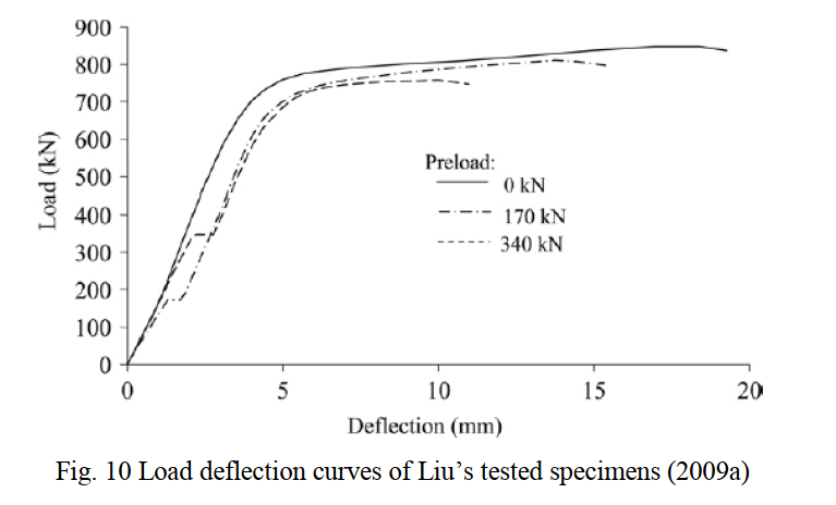
Regarding not offloading the beam wile strengthening causes an increase in deflection as can be seen in the image below, from this text "Experimental Behavior and Strength of Steel Beams Reinforced while Under Load", which was referenced in this text "Strengthening Steel I-Beams by Welding Steel Plates before or While Loading".
The graph also seems to suggest that the higher the pre-load, the less ductile the failure gets, which obviously is bad. The less ductile behavior also sort of confirms what I and human909 wrote about. The maximum deflection is reduced to about 50% as compared to a strengthening at relaxed state, but the yielding load is about the same in the graph.
MicrosoftTeams-image_25_tipf9q.png
 
You could use temporary, half story tall, threadbar post tensioning to jack the beam. Then install conventional flange reinforcing. You'll have to plan it out such that the deviators and such don't interfere with the installation of the permanent reinforcing but, with a little creativity, that should be resolvable.
 
Thanks for the suggestion!
It seems like a smart thing to do, but I am not sure how you mean, could you post an image or link that explains it more? It would be greatly appreciated!
My guess is that you mean something like the suggestion that I posted further up in the thread, but instead of prestress cables etc, I use a threaded rod (welded at the end of a rebar/plain steel) and tighten the rod with bolts to achieve the tension force , then when the welding is done the tension can be released. Is this what you meant?
 
First, some preliminaries:

1) how many beams do you need to reinforce?

2) how much depth below the beam is available for reinforcing?
 
About 10 beams

There is some ventilation and electrical "trays" /"ladders" close below some of the lower flanges. But regardless of methods these will need to be moved -(temporarily at least) to access and reinforce from below. I'll have to check with the client, but with that said, maybe 0,5m for temporary, for permanent just a few decimeters

If they refuse any measures below there will almost be to many restrictions...
 
Human909,sorry I was more referring to lifting it up with the cables. Analyzing the current loads vs future with respect to the reinforcement is critical. Often we get to reinforce before the new loading is added, but there are cases like this where the beam is already heavily loaded prior to reinforcement.

XR250, yes I should've said round bar, good catch. Very easy to use and cheap.

Seems like the biggest hurdle here is how to de-load the existing beams. The reinforcing will be easier to detail once that is solved.
 
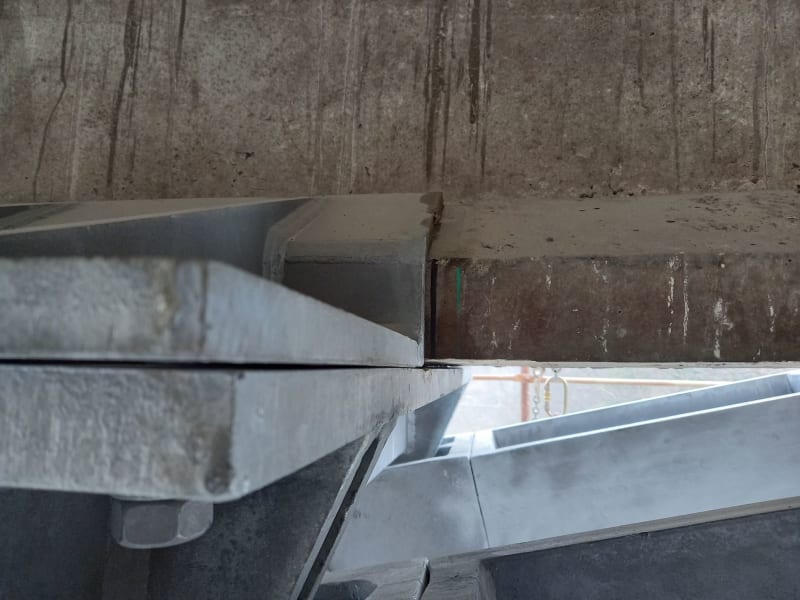
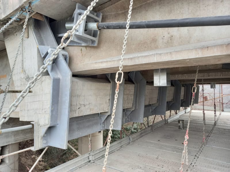
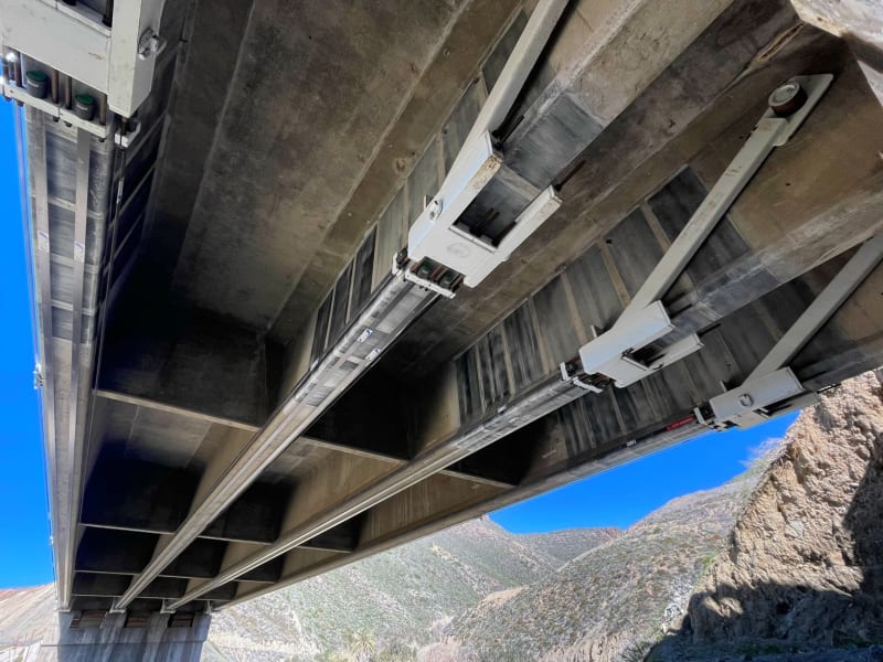
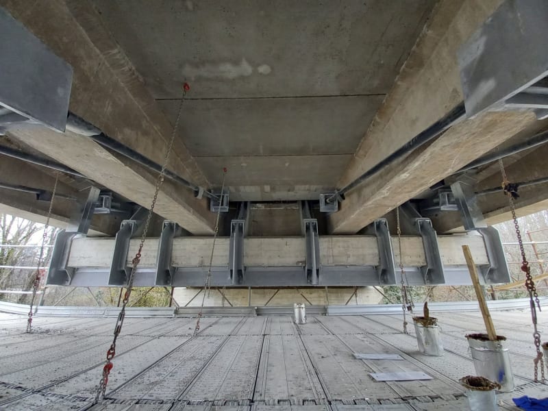
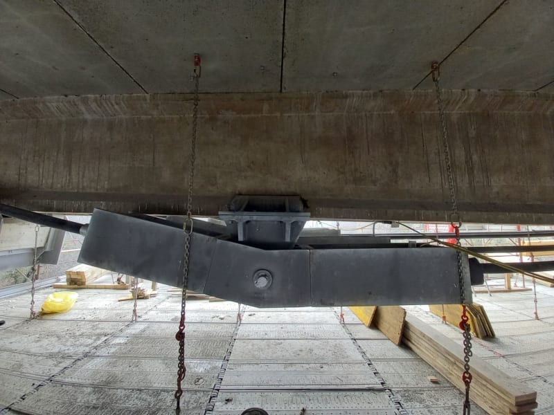
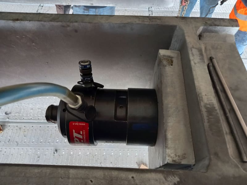
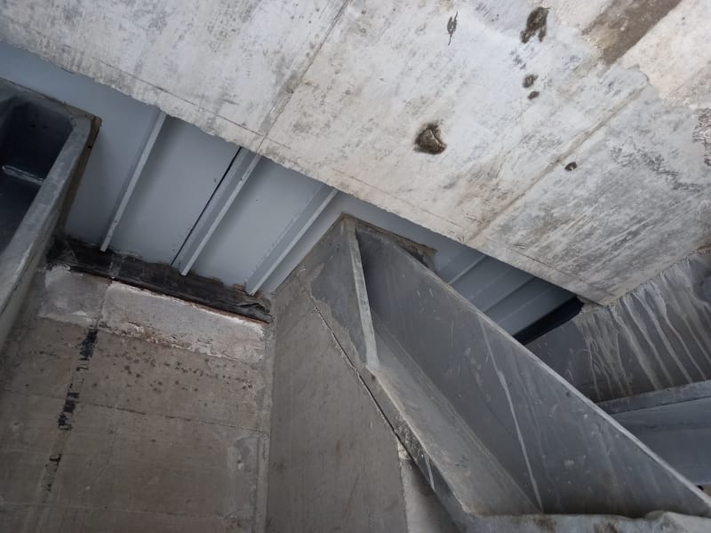
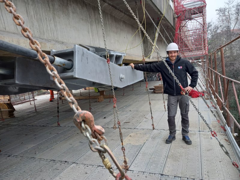
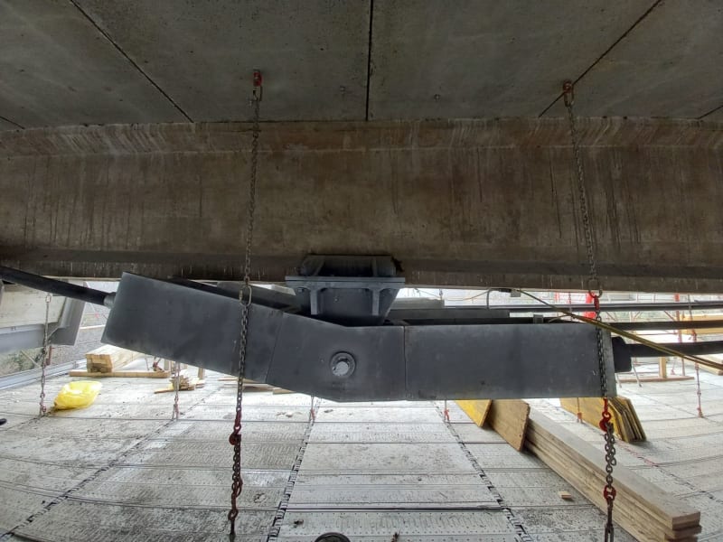
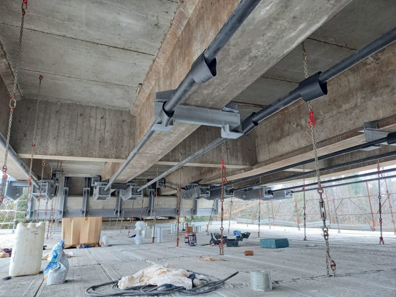
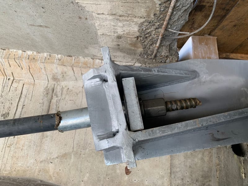
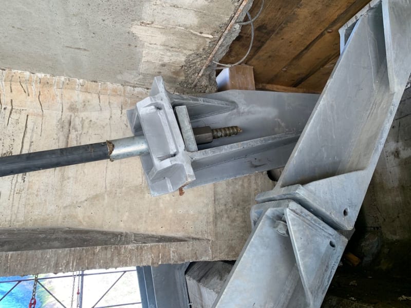
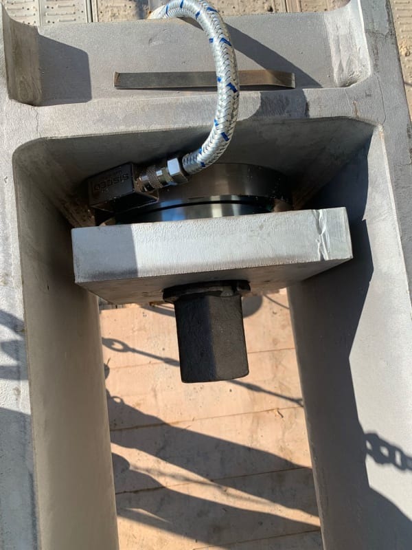
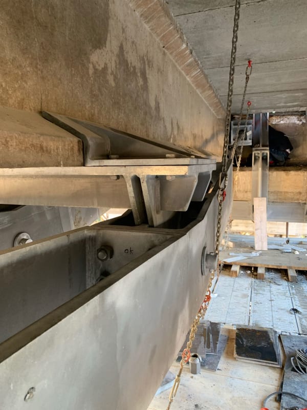
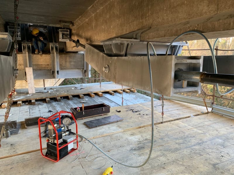
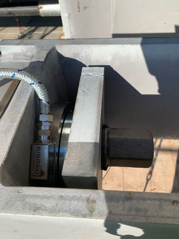
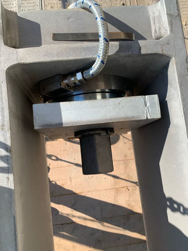
This procedure might help you out - from Italian friend
same concept could be adopted to steel girder

1677172424738_1_p3opeq.jpg
1677172425067_1_xhpt78.jpg
1676867833812_gaznta.jpg
1677172423239_rdebu6.jpg
1677172423247_1_p6wy6i.jpg
1677172418435_d1vpxr.jpg
1677172425040_a5wzrd.jpg
1677172425746_d90exk.jpg
1677172423247_qzwpvn.jpg
1677172424738_yjiz56.jpg
1677172425067_n5u2cz.jpg
1677172425452_tmrgc7.jpg
1674303465021_vzw86f.jpg
1674303464440_xran5o.jpg
1674303463936_1_hyzoyw.jpg
1674303462772_h0uvfp.jpg
1674303465678_ghpm8g.jpg
1674303435196_cpjifh.jpg
1674303464877_s1bf7q.jpg
1674303463936_sx57gz.jpg
1674303460226_ccgnmc.jpg
 
OP said:
I'll have to check with the client, but with that said, maybe 0,5m for temporary

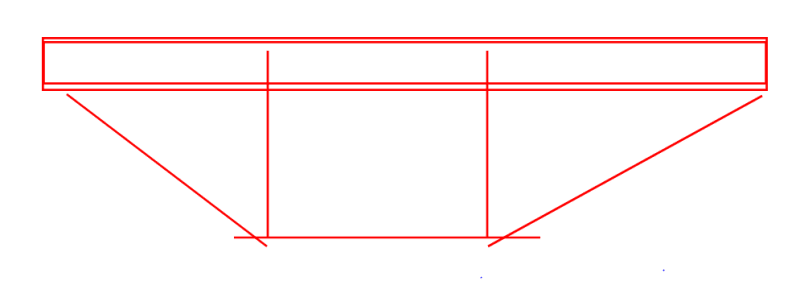
500 mm would neuter my idea. I was thinking of something more on the scale of the sketch below. More of a "post-trussing" than a post-tensioning really, even though some light stressing would still be involved.

adn said:
This procedure might help you out - from Italian friend

That is super bad-ass. Thanks for taking the time to share it.

C01_my8zcu.png
 
I have not read every post in detail but I have a few thoughts.

If I understand the project correctly, you have existing beams and now you believe they will need reinforcing to handle new additional loads. Correct?

As already mentioned, the reinforcing will only get stresses from the new load. But the existing beam will have an increase in stresses from the new load added to the stresses from the existing load. There may be options to "play" with in that respect, like post tensioning. Another option is to reduce the load before you add the reinforcing.

But still, how much of the capacity in the existing beams are used for the existing loads?

FRP may be an option but it may depend on that the buildings purpose is. Fire and FRP don't match without additional stuff.

 
Yes, now that I "know better" that the beams should be somewhat unloaded before strengthening them the problem has boiled down to how to unload them prior to strengthening.

Thanks for the inspirational images! It looks very neat and is somewhat to the point I am thinking

I guess the "post-trussing" would work without to much post-tensioning since it would have a much higher bendning stiffness compared to just the beam, so any weakening during welding would drive the load to the tension cord in the truss?


Isidor_:
Show some side views (elevations) of some of the existing typical beams, so we can see what we have to work with and work around. Show dimensions, widths, thicknesses, stiffener locations and sizes, etc. so we see the actual beam section/size, properties. Show us some calcs. for existing conditions and for the new loads and moments and shears. You consistently show a very shallow tendon profile, which does not offer much improvement in beam strength, it mostly adds axial load to the beam. Do you have access to the ends of your beams for this reinforcing work? Show a building detail at the ends of the beams, with surrounding bldg. materials/components, clearances, etc. The question..., how much room do you have for end bearings and work, beyond the end of the beam? Ideally, you would like the end bearings at the beam end and at/near the top flange. This gives you the max. potential tension rod harp depth, and max. upward loads on the beam, at the harp points. I would use high strength round bars/rods, not prestressing tendons because of the stretch and relaxation issues. You are going to have to shore and maybe even reshore at a lower level to unload these beams to make this work. You really must de-stress the beam and then apply the strengthening features, or you are fighting an uphill battle. The efficiency will come from good clean details, repetition (10 bms.) and a well thought out plan of attach. This just isn’t a simple problem, however you cut it. You might be able to shore/jack up right on the bot. flg. of the beam with the right planning and details.

The end brg. blks., same both ends, hook over the top flg. at the beam end, and are bearing on the top flg. and web, up near the top, and are welded in place. The ends of the tensioning rods are threaded with washer and nut on the end, through the brg. blks. and a turnbuckle toward the center of the beam. The center section (it’s a 3 part tension rod, 2 ends and 1 center rod) of the tensioning rod can be pre-bent for two or three harp point saddles at the beam C/L and at the .4L and .6L points +/-. The exact details depend upon your existing beam and what you have to work around.

Normally, we say that means and methods are the G.C’s. problem, but these kinds of problems reqr. a good deal of really good communication and cooperation btwn. the engineer/designer and those doing the implementation. Find a capable, trusted contractor and involve him at a fairly early stage of the construction planning, RE: his ideas, equipment, methods, how would he go about the implementation, what can you change to make his life easier, etc.
 
OP said:
I guess the "post-trussing" would work without to much post-tensioning since it would have a much higher bendning stiffness compared to just the beam, so any weakening during welding would drive the load to the tension cord in the truss?

I see the "post-trussing" as being nothing more than an alternate means of unloading and shoring the beam. You replace what is currently a high flexural tensile stress in the bottom flange of the beam with a truss top chord compression stress that ought to be an order of magnitude lower. This solves most of the problems that others have identified above. Stitch weld your bottom flange reinforcing into place as you normally would and move the post-trussing over to the next beam to be reinforced.

The fact that you have ten beams to reinforce will improve the economy of this solution as you can just use the one post-trussing thing repeatedly as you go, amortizing the cost of it. If it were a single beam being reinforced, this would kind look like the world's most expensive reinforcing solution. And maybe it still is, I don't know.
 
Status
Not open for further replies.

Part and Inventory Search

Sponsor