Eng-Tips is the largest engineering community on the Internet

Intelligent Work Forums for Engineering Professionals

  • Congratulations waross on being selected by the Tek-Tips community for having the most helpful posts in the forums last week. Way to Go!

Stress Analysis Help 1

Status
Not open for further replies.

MechE123abc

Mechanical
May 10, 2024
1
0
0
US
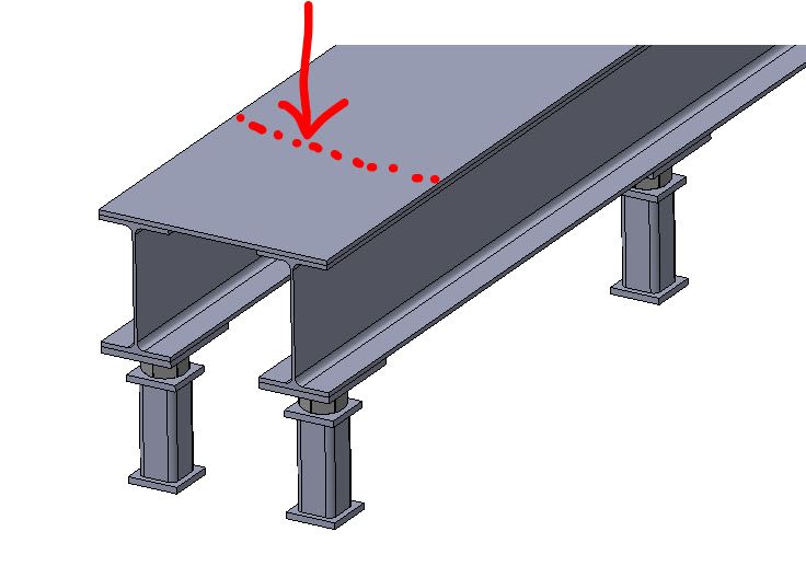
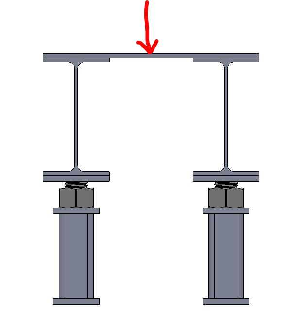
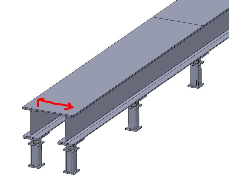
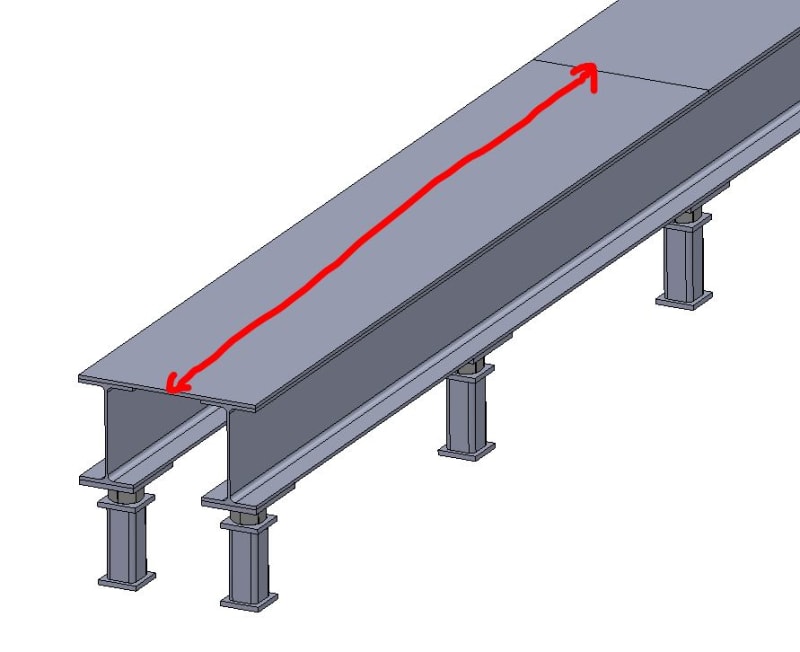
It's been a while since I've done structural stress analysis so feel free to explain as much as necessary. I am building this structure to act as a raised floor. The steel plate will screw into the flanges of the W-beams. I want to perform stress analysis on this top steel plate to determine if it will fail under certain loads. Let's say there's a point load of 10,000 lbs in the middle of the plate (where it's unsupported underneath) as shown in the pictures. From what I remember, I can check for bending stress and shear stress. If I take the two W-beams as the pinned supports with the span being shown in the third picture, I can determine max shear forces and max bending moments. However, what would I use as the cross section? I assume one dimension would be the height/thickness of the plate but would the other dimension be the full long side length of the plate? For example, if the thickness of the plate is 3/8" and the long length is 94" would the section modulus be 2.203 in^3? Not sure if I'm even evaluating this correctly.

1_r02ex4.jpg
2_qcuaef.jpg
3_j5dhll.jpg
4_i4bmka.jpg
 
Replies continue below

Recommended for you

Your section modulus would be the height and width of the span (the shorter **EDIT: LONGER** direction in this case). If it's a true point load it would be worth a quick pull through check as well, also don't forget about the plate prying at the connections.
 
This seems like more of a local check than an overall section modulus check. The elastic section modulus would be based on the cross section perpendicular to the span - which is going to be the long direction (parallel to the beams) and the thickness of the plate. Since that long direction length is so long - I would be pretty surprised if that controls the capacity here unless the plate is extremely rigid. I'm not sure exactly how I'd go about limiting the width to check the plate capacity in a more local manner though. Will be following this thread as others respond too
 
I don't think that the short direction length would be used for a section modulus calculation though - cross section is always perpendicular to span.
 
If I had a scenario like this, I would work it backwards. Based on the point load, span, yield strength, and plate thickness I would determine what the REQUIRED plate width would be and then decide if I was comfortable with assuming the point load distributes itself over that width.

If the required width is something like 5" then no problem. If something like 8' were required, you may consider thickening the plate. Ultimately the width you are ok with is up to your own judgement. Steel is ductile and can probably redistribute the load over a fairly large width, but I'm not sure what a good rule would be for determining that width.
 
Our good friend Roark has and answer for this. From Roark's Formulas for Stress and Strain:

temp_zrg202.png


(for a simply supported plate 4 sides, with 'a' as the long side. In your case you'd be looking at the far right hand table as a>2b is effectively simply supported 2 sides)
 
The whole thing looks wobbly. The beams should be braced together to prevent rotation.

The strength of the top plate depends on how and where you place the screws. Why screws? Bolts would be better. And the top flanges will stiffen the plate. What is the bearing area of the load? Strength of top plate is pretty indeterminate, but a conservative estimate can be made.


Status
Not open for further replies.
Back
Top