Eng-Tips is the largest engineering community on the Internet

Intelligent Work Forums for Engineering Professionals

Stress at a corner in a 90-degree Frame 3

Status
Not open for further replies.

SpaceEngineer4

Aerospace
Aug 8, 2023
12
0
0
US
Capture_i31vxv.png


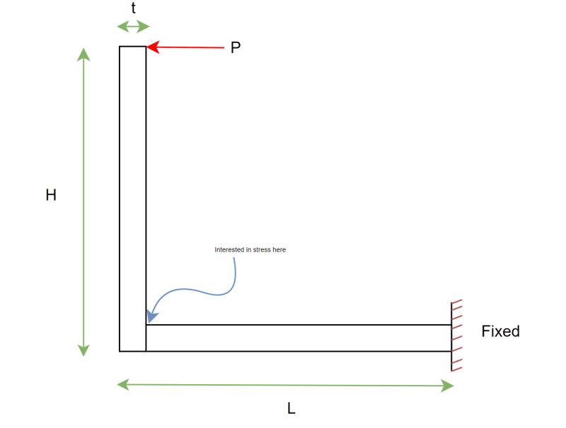
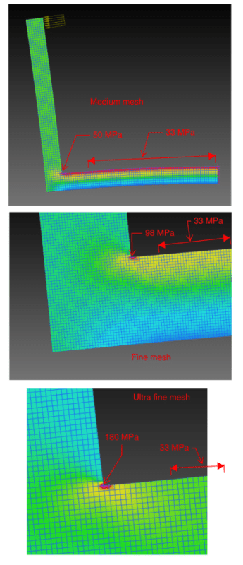
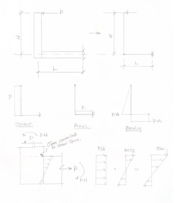
Salutations everyone. I've got a question regarding the stress in a frame, or one could call it a beam bent 90 degrees. Assuming the beam has the dimensions shown in the image, I'm having trouble doing hand calculations at the corner indicated in the photo. Obviously there are the classical bending moment contributions, Mc/I with stress concentrations. However, when I run the FEA on this continuous beam, I notice that there is a significant shear stress on the corner indicated in the photo. I did not expect this because according to beam theory, the shear stress on the outer fibers of a section should be zero. However, the shear stress may be very big in that corner. Could anyone help out with some guidance on how one might go about calculating stresses in a continuous beam/frame such as this? My dearest thanks to you all.

Cheers.
~Robert
 
Replies continue below

Recommended for you

is that two pieces or one ?

two pieces ... then the fasteners come into play, either two rows (to clearly carry the moment) or one row and "heel-and-toe" bearing stresses

one piece ... what corner rad ?

"Hoffen wir mal, dass alles gut geht !"
General Paulus, Nov 1942, outside Stalingrad after the launch of Operation Uranus.
 
One of the restrictions of beam theory is that it is applicable "away from supports". It's used anyway for lack of a better idea.
If you really need the stress at that point, I would think FEA would be the way to go.
Depending on how that assembly is made, there may be a small radius or fillet inside that angle, and I would expect that to affect stresses at that point considerably.
If minor yielding at that section is acceptable, I'd just go with the Mc/I and recognize there is some departure from reality.
 
If it is a sharp 90 degree corner, then the stress is in theory infinite. A FE model would show the same thing.

I think hand calculations get thrown out the window because there is no good reason that plane sections will remain plane in that corner.

 
The photo I included was only meant to be notional, and as I'm concerned with net section stresses I didn't have an interest in getting into the weeds with stress concentrations. Let's assume that this is only one piece...it is obvious to me that multiple pieces screws would come into play. What surprised me is that in doing the FEA on some variation of this frame, my shear stress in that corner was a main contributor to my von-Mises stress. In other words, the Mc/I bending stress (which matched between the hand calculation and the FEM) contributed, say, 5 ksi while the shear stress was, say, 8 ksi. Using Mc/I was quite inaccurate, predicting about half of the FE stress. It surprised me that I wasn't able to successfully analyze this using classical hand calculations... something like this seems like far too basic a design to resort to FEA for. After all, its almost just a beam. Many years ago, before FEA, I have to imagine it was possible to predict the stresses here with some degree of accuracy, no?
 
How are you able to determine that plane sections will not remain plane in that corner? Is it because the load has to change direction, which is "different" from your classical 1D beam? I also understand that per St. Venant's principal the Mc/I is not applicable directly near supports, but in a 1D beam you can get the correct bending stress reasonably close to the support (since in a cantilever, that's where you care about the stresses generally).
 
Before FEA, they had full-scale testing, strain gauges, photo-elastic stress analysis, brittle coatings, etc. In the olden days, some problems conveniently lent themselves to numerical solutions using finite-difference techniques as well. That specific geometry looks like it might be a good candidate for the photo-elastic approach.
In the olden days, if a geometry was common enough, and worth the trouble, somebody might eventually cook up an analytical solution. Even then, you might wind up summing double infinite series to actually get numbers out of it.
 
The absolute values of the stresses are irrelevant, I just put some random dimensions/materials/forces in here, but it goes to show that the stress approaches infinity at the corner (assuming it is a 'sharp' corner, which has its own problems).

Of course this all depends on how it's actually connected (e.g. maybe it's nailed, or glued, or whatever). But for a continuous material with a sharp corner, you can't ignore the stress concentration. And for a ductile material the stress concentration may have no real implications on the overall strength. It really depends on the details.

Capture_rymngd.png
 
and a linear FEA ...

whilst you "could" machine a sharp corner, plasticity would come into play.
practically you'd have some radius, the bigger the better ... but you're still likely to have plasticity effects.

I wonder what stress you're plotting ? wouldn't the stress increase along the vertical leg, the further you get from the load ?

"Hoffen wir mal, dass alles gut geht !"
General Paulus, Nov 1942, outside Stalingrad after the launch of Operation Uranus.
 
rb1957, this is plotting only the stress in the horizontal direction. There were a few comments earlier asking why it wouldn't just be stress = My/I, which would be accurate away from the corner but not near it. That's all the FE model was trying to demonstrate.

Agree with your comment about plasticity.
 
SpaceEngineer4 said:
I believe many of you are suggesting to ignore the shear stress in the corners. Any insight into why?

Because you posed this question to a bunch of building and bridge structural engineers, not aeronautics or mechanical engineers (though a few of them do come around occasionally). I don't believe you mentioned the shape of the cross section. If this were an I shape, we'd ignore the shear because the shape of the section doesn't lend itself to an interaction between the two. Even if it were a hollow box, you could still simplify it to assume the moment is carried in one set of flanges and shear in the other.

In a building structure that doesn't get to go through testing to verify the engineering before use, we have to be very conservative relative to other engineering disciplines. So most of our analysis techniques that we use in practice don't get into that much detail. And this frame in solid bar stock would be unlikely to be doing anything critical in one of our structures. Could be, but it would be an abnormal circumstance to be sure.
 
I think it would actually take extra effort to provide a sharp corner there. If it is a rolled section, there will be a natural radius in the corner. If it is welded you'll have some weld transitioning the corner...unless you grind it back square, but that takes time and money and won't be be done unless specified.

CDLD said:
What am I missing here?
Moment is P*(H-t/2).
Stress is My/I.

You're missing the P/A component. There is stress due to bending and direct axial load.
 
The sketch doesn't shown an axial load.
But if we're talking about the horizontal member, than yes you are right there is also tensile stress.
 
"I believe many of you are suggesting to ignore the shear stress in the corners. Any insight into why?"

it's also (with a bunch of caveats due to the simple shape shown) that peak bending stress is on the surface, where the shear stress is zero.

"Hoffen wir mal, dass alles gut geht !"
General Paulus, Nov 1942, outside Stalingrad after the launch of Operation Uranus.
 
CDLD said:
The sketch doesn't shown an axial load.
But if we're talking about the horizontal member, than yes you are right there is also tensile stress.
SpaceEngineer4 said:
Obviously there are the classical bending moment contributions, Mc/I with stress concentration

We're talking about the maximum stress at the corner, so yes, the axial load in the horizontal member is relevant. I'm sure we're all on the same page with this but I've included a sketch below to confirm.

SpaceEngineer4 said:
I did not expect this because according to beam theory, the shear stress on the outer fibers of a section should be zero.

This isn't a straight beam, its a frame with a 90deg bend. The maximum axial stress in the horizontal member is dumping a bunch of shear stress into the extreme fiber of the vertical member. In bugbus's images you can see the maximum axial stress in the top of the horizontal member extend briefly into the vertical member before the concentrated stress from the horizontal member distributes more evenly into the vertical member. There are the expected stress concentrations from the sharp corner, but I think the shears stress at the extreme fiber of the vertical member is also expected.

etips_ayczcy.jpg
 
Thanks for the contributions everyone!

SpaceEngineer4 said:
The photo I included was only meant to be notional, and as I'm concerned with net section stresses I didn't have an interest in getting into the weeds with stress concentrations.

I understand that in my simple diagram I depicted a sharp corner.... per rb1957' and bugbus' comments of course there would be some rad at the corner. Pick any radius and you'll see my point below is illustrated.

rb1957 said:
"I believe many of you are suggesting to ignore the shear stress in the corners. Any insight into why?"

it's also (with a bunch of caveats due to the simple shape shown) that peak bending stress is on the surface, where the shear stress is zero.

If were to add the rad in that corner and plot the stress components, you would see that the shear stress on that outer fiber (in the corner) is high relative to the bending stress, which is at the crux of my question.

phamENG said:
Because you posed this question to a bunch of building and bridge structural engineers, not aeronautics or mechanical engineers (though a few of them do come around occasionally). I don't believe you mentioned the shape of the cross section. If this were an I shape, we'd ignore the shear because the shape of the section doesn't lend itself to an interaction between the two. Even if it were a hollow box, you could still simplify it to assume the moment is carried in one set of flanges and shear in the other.

In a building structure that doesn't get to go through testing to verify the engineering before use, we have to be very conservative relative to other engineering disciplines. So most of our analysis techniques that we use in practice don't get into that much detail. And this frame in solid bar stock would be unlikely to be doing anything critical in one of our structures. Could be, but it would be an abnormal circumstance to be sure.
I get that I am asking the question to a forum of structural engineers, and so simplistic approaches are used with high factors of safety so thanks for bringing that to my mind phamENG.

~Robert
 
Status
Not open for further replies.
Back
Top