Eng-Tips is the largest engineering community on the Internet

Intelligent Work Forums for Engineering Professionals

Stress Concentration in D-Profile Shaft 3

Status
Not open for further replies.

sheafromme

Mechanical
May 1, 2020
25
0
1
US
Hello,
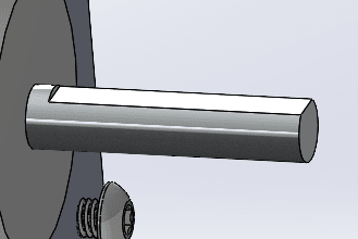
I'm having trouble determining how to account for stress concentrations at the root of the flat on a motor shaft due to overhung radial loading. I inherited a motor/pulley assembly that has an propensity for the shaft to snap off right at where it transitions from a D-shape to circular cross section. The pulley pictured below has a belt on it that applies the loading.
Mot_mubjgb.png


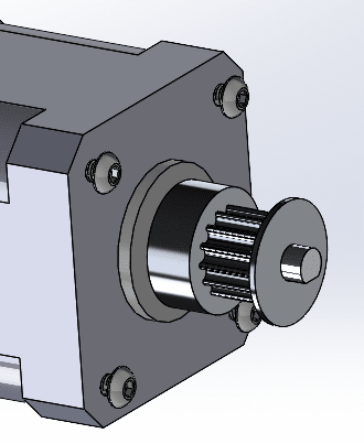
There is not a fillet where the shaft changes profile
sh_fkrjeu.png


I've looked through most of the resources I have here and I can't seem to find anything that addresses this particular situation. It' probably because it's not a great design...

So, I was just wondering how to properly calculate the fatigue life or at least how to account for the huge stress concentrations at that transition point due to bending.
Thank you!
-Shea
 
Replies continue below

Recommended for you

Though a very useful document worth keeping around, this is a bending failure, not a torsion failure.

Reducing the leverage to reduce the bending moment is good; reducing the tension in the belt to reduce the bending moment is also good.

Using a spring-loaded idler is a better long-term solution as it allows removing slots that can be used by techs to get the tension as high as they think it needs to be.

Blending out the flat to remove the sharp corner is still a useful change to make. The typical radiused undercut is usually to allow a more precise fit, but it does reduce the stress concentration.
 
Hi

The failure is the result of the maximum principle tensile stress causing the fatigue and that tensile stress is the resultant of both the over hung load and the torsional stress due to the torque. So with the information about torsion the principle stresses can be calculated using a mohr circle. At least that’s what I think.

“Do not worry about your problems with mathematics, I assure you mine are far greater.” Albert Einstein
 
Is there any indication that the set-screw - shaft joint has slipped? Set-screws have terrible durability so should be limited to alignment/clocking, not driving torque. I wouldnt be surprised if it slipped and overloaded the shaft.
 
Torsional stress is typically not fully-reversed every revolution,usually just a variation, bending stress is fully-reversed each turn of the shaft. I like the calculation methodology of ASME B106.1, which is a withdrawn standard, but still in use in the material handling industry where infinite life is based on the bending moment, and not the torsional moment.

shaft_eqn_uik9qk.jpg
 
Handling stress concentrations in your motor shaft transition can be tricky. To tackle this, consider using the notch sensitivity factor ('q') and exploring the stress concentration factor (Kt) specific to your design. These factors provide insights into fatigue life and the severity of stress concentrations.

For fatigue life calculations, check out methods like the modified Goodman diagram or S-N curve. Yet, given the unique challenges, consulting with a mechanical engineer for a finite element analysis (FEA) is a smart move. They can simulate stress distributions and suggest modifications for enhanced resilience.
 
The end of the flat is clearly causing a very intense stress concentration. You can attempt to calculate it but the stress concentration factor required to converge on reality is going to be on a very steep part of a curve somewhere. Maybe the value of the math is to back-calculate the stress concentration factor based on real life data. The failure is driven by the alternating stress, considering how far the crack propagated before finally snapping off.

I agree with flipping the pulley (possibly halving your bending moment) and reducing the belt tension. Adequate belt tension with synchronous belts is generally not as much as you'd expect if the job is pure torque transmission. Tugboat's idea for the shoulder spacer is good, but it does require a way to draw it down hard from the shaft end and the motor bearing inner race needs to be mounted against a shaft shoulder to support that. But above all I'd be hammering the motor vendor to blend out the end of that flat and not leave the sharp step. Or rework them yourself, and make sure that the rework operation leaves the machining lay marks in the axial direction of the shaft, not across the shaft. Ideally you'll be able to get that done with minimal undercut.
 
This D shape has some similarities to a keyway

There are 2 traditional methods for machining the end of a keyway as shown at figure 1 page 2 here (a) end-milled or profile keyway; (b) sledrunner keyway
keyway_pla8pi.gif


I think each of these would have an analogous approach that could be applied towards transitioning from the D shape shaft profile to the circular profile.

I'm not sure which is the more favorable reduction in stress concentration.

geesaman.d said:
Or rework them yourself, and make sure that the rework operation leaves the machining lay marks in the axial direction of the shaft, not across the shaft.

That sounds similar to the sledrunner approach to me

EDIT - I wonder if the end-milled might be doable without removing the rotor to save time? EDIT 2 - although I guess rotor needs to be held more stationary than bearings can accomplish and not sure how much load we want to put on the bearings. Maybe a chuck on end of shaft would help those things, or maybe it's just a bad idea to even attempt machining the shaft without removing the rotor (I leave that to others more mechanically inclined than me to decide).
 
Just a dremel and a grinding bit and 30 seconds or less would ease that sharp stress riser. Not even a lot of skill - just erase the corner and stop.
 
Dremel is suitable for the sledrunner. It would probably require disassembly of the motor to get enough working room for the wheel that close to the motor frame. But maybe disassembly is inevitable anyway? (I wondered about that in "edit 2" of my post timestamped 17:18)
 
Using a radiused end mill to cut the flat would be a improvement but geeaaman brought up the direction of the surface finish. Utilizing the side of the mill would provide the correct orientation of finish.

However, these solutions would require manufacturing new motors with correctly specified shaft features. A little hand finishing can be done in the field and *may* solve the problem.

A third option is to make a new pulley that extends past the step with a close or interference fit. In the case of the close fit, utilize some retaining compound to make it like an interference fit.
 
About the third option: The stiffness to cantilever from the tiny projection is unlikely to be enough to work. Essentially it would have to act as if the remainder of the shaft was cut off. It looks like a 1/3 diameter long engagement would be supporting a load about 5 diameters out.
 
3DDave said:
The stiffness to cantilever from the tiny projection is unlikely to be enough to work. Essentially it would have to act as if the remainder of the shaft was cut off. It looks like a 1/3 diameter long engagement would be supporting a load about 5 diameters out.
So I think you're saying it's not practical to support the shaft from the end during machining, and therefore not practical to work without motor disassembly. That was feedback I was looking for, thanks
 
This is IMO a deceptively complicated fatigue problem.

The belt tension will cause what is effectively a static bending load on the shaft. Then of course, there is also the torsional shear stress on the shaft.

But because the shaft is not symmetrical, as it rotates around, the effect of the Kf and the stress state will change. And the variation of the peak torsional stress will not be in phase with the variation in peak bending stress, because the peak bending location will occur on the "opposite" side of the shaft every 180 degrees of rotation.

So what you have is a complex, multiaxial stress state with fluctuating (non-constant mean stress) level, and the fluctuation is mutually asynchronous.

Basically, one of the most complicated scenarios you could have.

Even if you could find a Kt for a stepped shaft in a handbook like Peterson, I doubt you could find a solution that covers all of the orientations of the shaft you need through the load cycle.

If I were set on predicting a fatigue life instead of redesigning the assembly, what I would do is develop a basic FEM for the shaft and get results from the loads in maybe 10-20 orientations.

Then I would pick a couple points on the shaft and develop a repeated duty cycle, mapping out the stress variation over time. Then I would apply the SEQA method or maybe even critical plane methodology to cover the complex fluctuating multiaxial damage accumulation.

They key thing here is that if you can correlate the predicted life to the life you've seen in service, you'll know your prediction methodology is decent.

So then you could repeat your analysis with different levels of mean and alternating stress to figure out what the load limits are in order to meet whatever service goal you have.


Then I would want to compare my predictions to the in-service data.

Keep em' Flying
//Fight Corrosion!
 
Just looking at the photograph unless it’s a trick of the light the crack initiation point appears to be at shiny bit on the shaft of the motor going into the motor body which could well be on the top of the motor flat looking at the other half which is held in the OP’s hand. There are possibly some other crack initiation sites around about 200-270 degrees from the first one I mentioned. I would start with a Mohr circle based on the shaft on its maximum BM at the shaft flat.


“Do not worry about your problems with mathematics, I assure you mine are far greater.” Albert Einstein
 
electricpete said:
That sounds similar to the sledrunner approach to me

Yes, I'm advocating for a sledrunner type end finish here. And the machining/grinding lay marks be axial, which is normal for a sledrunner cut. I think that and reducing the bending moment will put this to bed.
 
Status
Not open for further replies.
Back
Top