Eng-Tips is the largest engineering community on the Internet

Intelligent Work Forums for Engineering Professionals

Stress in Cover Plate in Uncracked Concrete Beam 1

Status
Not open for further replies.

MegaStructures

Structural
Sep 26, 2019
366
0
0
US
Hello,

I need some help determining the stress in a "stiffening beam" at service level loads. At the service level moment, the concrete is uncracked. I'm not exactly sure why, but the fact that the concrete is uncracked has made this analysis extremely confusing to me, so I wanted to get a confirmation that my method is accurate.

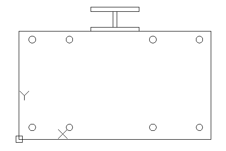
So, I have a concrete beam with rebar on bottom and top and an additional steel reinforcing beam anchored to the top of the concrete beam. I have created a detailed FEM that shows the force in the steel beam, and I am trying to develop a hand calculation to verify my results. I believe what I need to do is the following:
[ol i]
[li]Calculate transformed areas of rebar and steel beam[/li]
[li]Find centroid of composite section using the moment area method[/li]
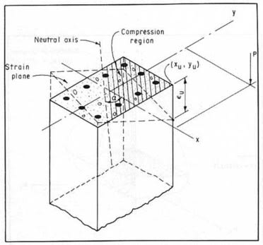
[li]Calculate the transformed moment of inertia using the calculated centroid, since concrete is uncracked I would use the entirety of the concrete as part of the MOI, not just the compression side[/li]
[li]Calculate stress as sigma=MY/I, since the section is elastic[/li]
[li]Calculate the force in the stiffening beam by multiplying the area of the stiffening beam by the stress at the extreme fiber of it[/li]
[/ol]

One of the difficulties I am having is that when I do this I am not getting the forces in the cross section to balance out. I am including forces for all rebars, the stiffening beam, the compressive component of concrete, and the tensile component of concrete. A couple things I'm wondering is:
[ol i]
[li]Should the Whitney stress block be used at strains less than 0.003, or is the stress-strain relationship of concrete significantly different at this point?[/li]
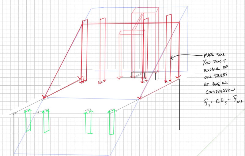
[li]Should I calculate the area under the stress diagram as a trapezoid instead of a rectangle (account for reduction in stress at the bottom of the stiffening beam)?[/li]
[/ol]

And now finally I must ask if there is a different method that I should be using instead and is there a excel file or other reference that I can use as a tool for checking my work and speeding up the analysis process?

“The most successful people in life are the ones who ask questions. They’re always learning. They’re always growing. They’re always pushing.” Robert Kiyosaki
 
Replies continue below

Recommended for you

The Whitney stress block is used for ultimate load calculations - at service load levels you just assume a linear stress/stain curve.

P.S. Why don't you just embed the image in your post instead of making people download it.
 
Hi Retrograde!

So below strains of 0.003 I should find the force in concrete by calculating the area of the "stress triangle" (1/2*height*max stress)?

I tried and tried to embed the image, but the purple camera button failed me. For some reason I'm getting no response from it. I would blame it on user error, but I'm typically a good clicker, I swear!

“The most successful people in life are the ones who ask questions. They’re always learning. They’re always growing. They’re always pushing.” Robert Kiyosaki
 
Yes - the "stress triangle" is the correct approach.

Cross_Section_zkxivs.png
 
The procedure that you propose is correct.
Be careful that concrete is not really linear up to a strain of 0,003, it starts to show significant nonlinearity at a strain of about 0,0015. But you should be well below that if the section does not crack.

OP said:
Should I calculate the area under the stress diagram as a trapezoid instead of a rectangle (account for reduction in stress at the bottom of the stiffening beam)?
I do not understand this, could you explain?

OP said:
One of the difficulties I am having is that when I do this I am not getting the forces in the cross section to balance out.
I know it may sound weird, but maybe you forgot something by accident. For example, parallel axis theorem for the concrete section or that stresses in steel need to be multiplied by the ratio of elastic modulii (it happened to me before).
 

Hi Mega structures ,
Your approach is reasonable. But in order to perform uncracked section analysis, make sure the tension stress developing at extreme fiber of conc. is less than axial tensile strength of concrete
Eurocode allows the use of mean axial tensile strength of concrete (fctm ; which fctm= 0.30* fctk**0.67 )for uncraked section analysis.
If Fct greater than fctm , you are expected to perform cracked section analysis.
...


He is like a man building a house, who dug deep and laid the foundation on the rock. And when the flood arose, the stream beat vehemently against that house, and could not shake it, for it was founded on the rock..

Luke 6:48

 
Assuming linear stress distribution in concrete solved my issue, the forces now balance! I now realize how silly I was for using the elastic method to find stresses and the Whitney stress block for concrete forces and being confused that the values didn't match up... Hindsight is 20/20 and all I suppose. Obviously not demonstrating a strong understanding of concrete behavior on that one.

I am clearly a bit rusty on my concrete material models and have more questions. Hopefully you all are willing to help me a bit more. If I now assume that the concrete is cracked (to match the FEM assumption of 0 tensile strength in the concrete), I am unsure how I should confirm that assuming linear elasticity is still valid or not. Section 2.3 of Mccormac shows that for a cracked beam elasticity can still be assumed, but doesn't expound on how it's determined that the service loads don't exceed the loads that allow this assumption to be valid.

I assume that what I need to do is check the strain in the concrete at the service load and ensure that it is still less than 0.003/2 at the given service loading?

If that is true, I still don't quite have a grasp on how I can do that. This is what I believe I need to do, but want to confirm:
[ol 1]
[li]Assume a value for c, to be iterated[/li]
[li]Calculate transformed MOI, assuming the concrete on the tension side of the neutral axis does not participate[/li]
[li]Iterate c until moment of areas equal[/li]
[li]Calculate the steel stress using elastic method (σ=My/I[sub]transformed[/sub])[/li]
[li]Calculate concrete stress using elastic method (σ=My/I[sub]transformed[/sub])[/li]
[li]Calculate steel and concrete force using F=σ*A[/li]
[li]Calculate the strain of the concrete to ensure it is less than 0.0015 (half of 0.003, use formula ε=σ/Ε)[/li]
[li]If the concrete strain is above 0.0015, just panic??? Not sure if the Whitney stress block is valid here of if there is a transition zone[/li]
[/ol]


“The most successful people in life are the ones who ask questions. They’re always learning. They’re always growing. They’re always pushing.” Robert Kiyosaki
 
Please take down the link that you shared with us! I feel like it violates the copyright - there is no need to share the whole book, you could have paraphrased the part that is important.

That is a tough question - it depends on what you're trying to achieve.
Sometimes I got good results way past where linear stress-strain is supposed to be valid - for example when I tried to calculate the curvature at yield.
I guess that I'd advise you to use a more detailed model in cases where it is not clear (this should not be that hard to do in a spreadsheet).
If you need the actual stresses I feel like you need to be quite low on the strains for linear model to be valid (maybe less than 0,1 %, I'm guessing here).

You do not need to iterate the compression size if stress is linear. From equilibrium it follows that first moment of area above the neutral axis = first moment of area below the neutral axis (for transformed section of course). From that you get a quadratic equation for c. it becomes a bit more complex with axial force though.
Stress in steel needs to be multiplied by n! So it's σs=n*My/Itransformed

Do not use stress block, forget about it for anything other than calculating capacity. Use a model that's valid for any load level if linear behaviour is not good. The code has to have a model for that, eurocode and fib have it... In that case you need to guess c and do it in a way that you mentioned.
 
MegaStructures:

A true general section analysis involves 3 unknowns:

Start with a general strain function that assumes plane sections remain plane, which leads to a linear strain variation:
e(x,y) = A x + B y + C

Plugging in some things we know regardless of the section or stress state:

1. e = 0 at the neutral axis

0 = A x + B y + C
or
y = -A/B x + -C/B <== This is the slope intercept form of the equation defining the line of the neutral axis

dy/dx = -A/B <== This is the slope of the Neutral Axis

Assume alpha = the rotation of the neutral axis counter clockwise
Tan alpha = A/B

A = B Tan(alpha) ---- Equation 1

2. e = e,max at the compression fiber furthest from the neutral axis, call this point (xu, yu).

e(xu, yu) = e,max = A xu + B yu + C

insert Eq. 1: e,max = B Tan(alpha) xu + B yu + C

Solve for C: C = e,max - B (xu Tan(alpha) + yu) ---- Equation 2

3. Substitute Eq. 1 and Eq. 2 into the general strain function and reduce

e(x,y) = e,max + B[(x-xu)Tan(alpha)+(y-yu)]
Screenshot_2024-06-21_110400_oskt3m.jpg


Here the 3 unknowns are:
e,max = maximum extreme compression strain
B = equation constant
alpha = counter clockwise rotation of the neutral axis

If you define your sections using vertices and straight lines then (xu,yu) should always be one of the vertices, and it will be the vertex that is the furthest from the neutral axis on the compression side.

--------------------------------------------

Relate strain to stress via material curves

That defines the strain in the general section, once you have strain then you need to apply the material specific stress-strain curves to the various sections:
For steel there is:
linear-perfectly plastic model where f,steel = e*Es for e <= e,yield and f,steel = Fy for e > e,yield
linear- with strain hardening

For concrete you have a lot of options:
PCA Parabolic-constant:
f,cip = 0.85f'c [ 2 (e/eo) - (e/eo)^2] for 0 < e < e0 and f,cip = 0.85 f'c for e >= eo
eo = (2 ( 0.85 f'c))/Ec

Hognestad's - Parabolic-Linear Curve which is similar to the PCA curve except when the strain equal eo the stress reduces linearly up to a strain of eu = 0.0038

Eurocode has a linear-constant and a parabolic-constant stress block that you could also adopt.

-----------------------
Perform the double integral of the stress fields to determine axial forces and moments

f(x,y) = stress functions, determined by substituting the strain function into the material strain-stress models

P = ∫∫f(x,y)
Mx = ∫∫f(x,y)*y
My = ∫∫f(x,y)*x

Note: For Mx and My be careful here with sign conventions you may need to make either y or x negative to be consistent with your chosen sign convention.

-----------------------
General numerical solution process:

Guess values for the three unknowns

Determine P, Mx, My <--- this step is rough, I have landed on doing piecewise integrals using green's theorem assuming all sections are defined by linear edges between vertices.

perform statics checks of your determined loads against the applied loads, everything should sum to 0. If the checks fail using your numerical method of choice determine next guess for the three unknowns. Newton-Raphson is one method but you'll need to be careful as the nature of the bi-axial problems leads to a lot of "flat" areas in the solution curve which can land you into an infinite loop with the NR method. There is also the modified N-R Method as well as some of the gradient descent methods that can take a little longer but work also.
 
For Single axis bending problems you then know alpha so the problem reduces in degree to a 2 unknown problem.

For single axis bending and simple shapes like rectangles the double integrals can be simplified significantly, down to mostly standard geometric formulas.
 
I made a quick example, hope it helps. It's the simplest possible situation, but I guess you can get the idea. It's eurocode based, but it's the same thing.
001_xg95yh.png
 
hardbutmild - I don't see a file attached

After reviewing ACI I see that a linear stress-strain assumption is valid up to 0.45 f'c, so I'll attempt the solution first assuming linear elastic behavior and make sure the strain is below that limit. Other sources, like Reinforced Concrete by Park and Paulay 1975 state that concrete can be assumed to behave linearly up to 0.7*f'c and can be accurate up to as much as f'c. To be safe I will use the lower values in ACI and if the stress in the concrete exceeds 0.45f'c I will perform a two-step calculation, one step up to the proportional limit (0.45f'c) and then continue using Hogenstad's parabolic model.

“The most successful people in life are the ones who ask questions. They’re always learning. They’re always growing. They’re always pushing.” Robert Kiyosaki
 
Celt83:

Great breakdown! A little bit intimidating and probably overkill for my application to actually integrate over the cross-section; I appreciate the effort you put into the post! Thanks for the reference to Hognestad's, I had the equations written down from my old class notes and did not label where they came from!

Edit: I'm actually now realizing that if I intend to use Hognestad equation for stress-strain of concrete I will have to integrate over the cross section. Pretty easy for a rectangular section I suppose.

“The most successful people in life are the ones who ask questions. They’re always learning. They’re always growing. They’re always pushing.” Robert Kiyosaki
 
Also for the bars in the compression region just be careful you don't double dip on the stress there, I've found it easiest to get the concrete force assuming the reinf. is concrete then reduce the actual stress in the steel by the equivalent stress in the concrete at the same location since the force from the concrete stress times the bar area is already accounted for in the concrete force.

Screenshot_2024-06-21_114356_zj4vms.jpg
 
Status
Not open for further replies.
Back
Top