Eng-Tips is the largest engineering community on the Internet

Intelligent Work Forums for Engineering Professionals

Stress in lifting lug is above yield 4

Status
Not open for further replies.

Mr_Curious

Mechanical
Jul 14, 2020
39
0
0
RU
Hello Dear Experts.

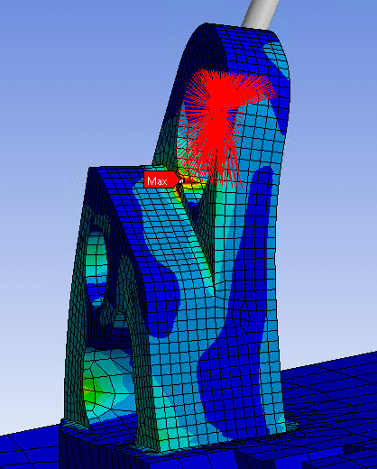
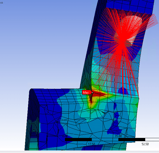
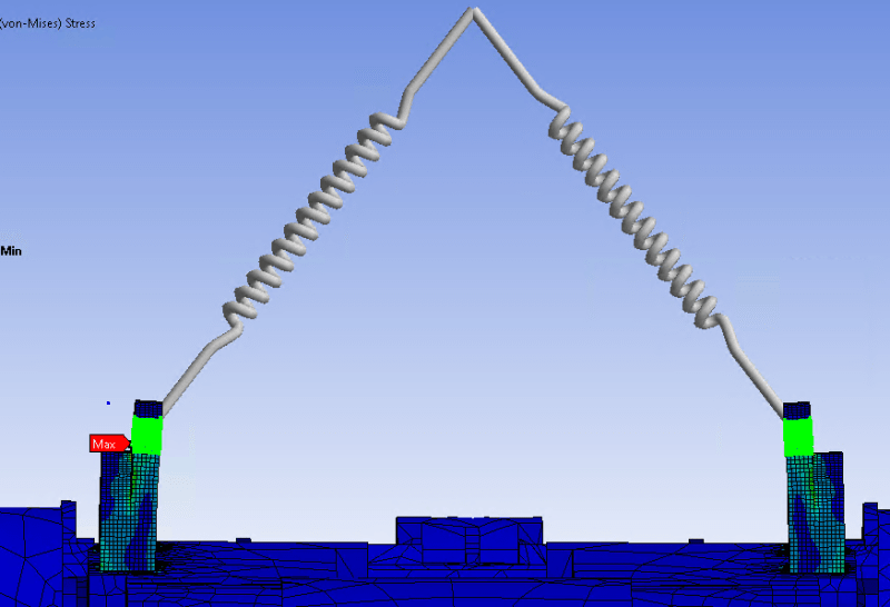
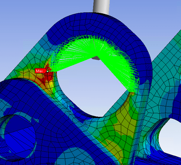
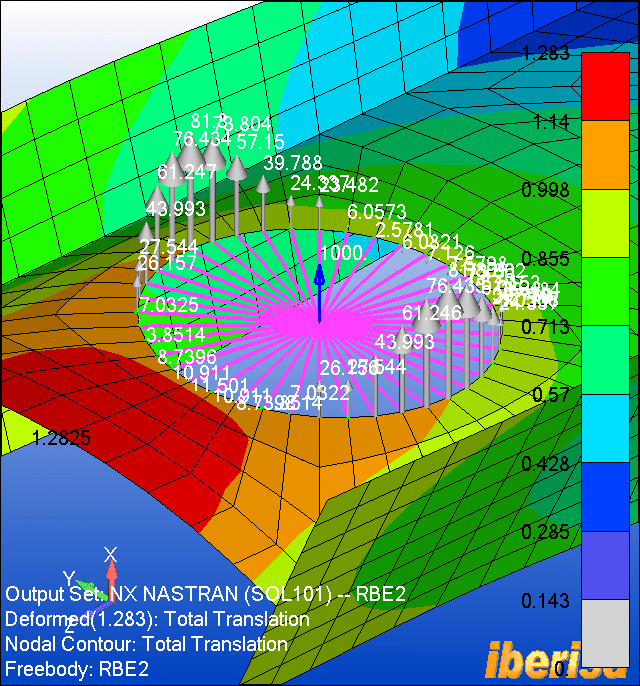
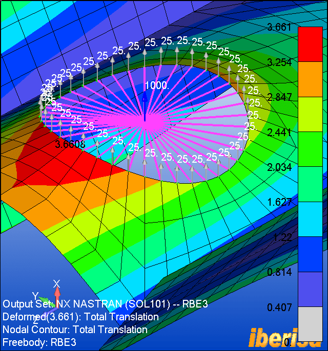
I have a construction with lifting lugs. FEA analysis showed an area with the stress in lifting lugs higher than yield strength. The area is shown in the picture below (red color). The lugs were tested in real-life successfully. But I need to write a conclusion for my FEA analysis describing why this red zone does not dangerous. (real-life testing is not enough).
Help me please, what knowledge or books can I refer to?
Screenshot_2_deb1mb.png

Screenshot_1_ieu3m9.png
 
Replies continue below

Recommended for you

Don't know what your FE model is doing. I was involved in a court case about 50 years back where a local engineer had used shear friction for designing a connection. He was correct, but the engineering prof that was on the 'other' side had run an FEM model on the steel dowels and had concrete stresses in excess of 13ksi. His model couldn't adjust to the change in stiffness with yielding, and he couldn't answer the question of 'what happens if the concrete yields locally...

Rather than think climate change and the corona virus as science, think of it as the wrath of God. Feel any better?

-Dik
 
Is plasticity included in your analysis ? Did you perform the mesh convergence study ? If you are sure that this result is correct and that it’s not caused by modeling assumptions (defeatured geometry, simplified boundary conditions) then you can conclude that the part yields locally. It happens in many structures and often doesn’t indicate failure unless the yielding zone becomes too large or fatigue is involved.
 
The rigid "wagon wheel" element is connected 360 degrees around the hole - this is not realistic.
Rigid elements connected to a hole boundary usually lead to rubbish stresses at the hole surface.
The interior mesh looks horrible; hope those are second order tet elements.
What is the direction of applied load?
What is the material? Linear or plastic stress-strain curve input?

 
Mr_Curious

I would not worry about localised high stresses crossing yield at the singularity/abrupt change in cross section. I would run elastic perfect plastic material model (zero tangent modulus)run to just check how much area exactly going above yield. But from the pictures I see, it's only 1 or 2 elements going above yield which suggest nothing but local yielding and not the instability of entire lug. Another thing as SWComposites pointed out, applying coupling to entire hole surface is just plain wrong. The rigid elements of RB3/RB2 will introduce lot of stiffness to the lug hole surface and hole surface deformation depends on the pin reference node. I would only apply coupling to area which is actually in the "touch" like shackle pin touching the lug. Or you can model rigid pin and apply the force to this rigid pin which will automatically take care of the contact area.

 
Screenshot_3_xnhtni.png

Screenshot_4_bs3syr.png

Screenshot_6_qog3fa.png
Screenshot_8_i1d9pc.png


I used linear material, steel. I performed mesh convergence and I am sure about that. The mesh is second-order elements.
The structure is lifted by 2 fabric slings pulled through the lifting lugs. And the most dangerous case is 90 degrees between slings is considered.
As slings, I used the Spring tool in Ansys with a very high stiffness of 100000 N/mm, and behavior as Rigid.
Actually, I am not sure about those settings. Couldn't find anything relating to this analysis on the internet.

Does anybody know what settings should be used for stiffness and behavior?

Yes, I understand that part yields locally happens pretty often. For example, using a hook instead of fabric slings leads to the area of contact will be much smaller so there will definitely be yield. But how to write about it to people who disagree with the presence of the yield in the analysis :)
 
Mr_Curious

It looks like the approver is not conversant with FEA. Otherwise he would have ignored the local high stress or would have suggested to perform elastic perfect plastic model to see is it really yielding.
Never mind. People not conversant with FEA are checking FEA reports which is not good. You need to put lot of justifications in report( sometimes literally need to teach the approver about FEA result interpretation). But then sometimes there is no option but to get FEA education from non-FEA guy.

One thing you can talk about in the report is how the area of yielding is very local-limited to only 2-3 elements. Try to limit the colour plot to yield stress(stress above yield shall be shown by gray/your favourite colour) and show how many elements are going above the yield and say these are stress concentration due to the abrupt change in area and local yielding will redistribute the stresses and structural integrity of lug is maintained (as I can see very local stress in images in your post). Show him how the max stress to stress away from max stress ratio looks like.

If not convinced, do a zero tangent modulus analysis and show the plastic strain plot (adjusted to 0.2%). If there are no strain which I definitely see from you stress plots that there is not going to be much plastic strain, you are saved.

Hope this helps.


For wires or ropes, you can use tension only springs. Verify the forces in the spring.

Use of beam or truss element is good option. Take a look at this link.
 
This maybe a silly question, but why would you use FEM for a solution to this problem?
+

Rather than think climate change and the corona virus as science, think of it as the wrath of God. Feel any better?

-Dik
 
FEA like this will not give useful results for lifting lugs, they give pretty pictures with no relation to reality (the level of detail required for useful results would involve a much more complicated model).

The correct way to do this is with hand calculations related to a code. There are numerous codes that provide equations/ factors such as ASME BTH, DNV-2.7-1/3 and many, many others.
 
I really didn't think it was silly, but in case I was wrong, I was covering all options. [pipe]

Rather than think climate change and the corona virus as science, think of it as the wrath of God. Feel any better?

-Dik
 
dik and SSCon

No. This is not silly question. Its quite valid question and I agree because we do mainly analytical calculations for the padeyes using DNV-ST-E273, API 17D etc. But guess what we also do lot of lifting scenario analysis to check whether the padeye attached structure is ok or not for lifting in offshore /onshore/in sea. Then some padeyes are easy to calculate and some are not. First thing comes to mind when I heard Padeye is calculation. But if its lifting scenario then we have to open the window of FEA software and close the calculator/excel/Mathcad. It would be judgment day of my FEA career when all things are calculable by analytical calculation.[tongue]

Now I also have silly question-Why so much silly questions are asked when one see pretty pictures of FEA in report? Or rather taking OP's question why would the checker is uncomfortable about local high stresses at small locations crossing yield when he sees the pretty pictures of FEA? Of course he will be if OP has not given the proper reasoning behind it. But then is that suggest something else?

SWComposites
My humble opinion- The abuse of FEA has roots in the designer's incompetency to defend his simple design and analyst's incompetency to segregate simple vs complex design. The onus remains same on both.

Anyway what I see from pictures is not regular padeye. There is tiny distance between the padeye hole center and its base. Regular padeyes are long for this distance. Also there is another plate attached just below the "oval hole" or eye of the padeye.

Would like to see/hear different opinion/s.

 
Dear Mr. Curious,
I see you are using rigid RBE2 elements to transfer loads from rope to the lug hole, wrong!, caution here, this is the main reason of your stress results, please note when using rigid RBE2 elements all move like a rigid body, the full hole deform like a rigid body, then you will have high stresses in the region that are artificial, not real, theses stresses are consequence of the use of RBE2 elements.

To understand please visit my blog where I explain the differences between RBE2 & RBE3 elements:
• Deformed shape using RBE2 elements: you see the hole remains as a perfect circle after deformation.
rbe2-example_mlu7l6.png


• Deformed shape using RBE3 elements: the diference is clear, the hole deforms according its natural stiffness, RBE3 is a force link, where RBE2 is a displacement link.
rbe3-example_omzdmv.png


In summary, what I try to tell you is that stresses are a direct consequence of the element types used in your FE model, the way you apply loads & BCs is critical, not only a linear vs nonlinear analysis question, my rule is to reduce the use of RBE2 elements as much as possible and try to mesh connections without altering its stiffness artificially, OK?.

Best regards,
Blas.

~~~~~~~~~~~~~~~~~~~~~~
Blas Molero Hidalgo
Ingeniero Industrial
Director

IBERISA
48004 BILBAO (SPAIN)
WEB: Blog de FEMAP & NX Nastran:
 

It yields first time, and then it's elastic...[pipe]

Rather than think climate change and the corona virus as science, think of it as the wrath of God. Feel any better?

-Dik
 

I can't imagine what all of them might be, but I suspect it would be interesting. [ponder]

Rather than think climate change and the corona virus as science, think of it as the wrath of God. Feel any better?

-Dik
 
Thank a lot to everyone.

The issue has been solved. I presented a FEA with a standart eye-bolt and showed similar area of stress above yield.
 
Status
Not open for further replies.
Back
Top