Eng-Tips is the largest engineering community on the Internet

Intelligent Work Forums for Engineering Professionals

  • Congratulations waross on being selected by the Tek-Tips community for having the most helpful posts in the forums last week. Way to Go!

Strong wall at the end of a floor beam

Status
Not open for further replies.

AR2_Struc

Structural
Nov 15, 2022
3
0
0
US
I have a situation where I'm placing a 24" strongwall at the end of a wood beam. Overstrength forces bring the uplift/compression to 34-kips, requiring a Wide Flange beam. The strongwall is secured to the top flange of the beam with web stiffeners provided.

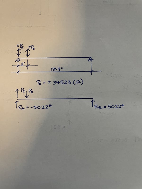
Given the proximity of the strongwall to the beam support (in this case an HSS column), a fellow engineer believes that the 34-kip uplift needs to be transferred directly to the column since the load will 'follow the path of least resistance'. I am in disagreement with this and believe that the beam will dissipate this force significantly through 'beam action', shown by the attached free body diagram. I argue that since the strongwall is securely anchored to the beam and not directly to the column, I should design the connection for the beam reaction and not the direct uplift force from the strongwall.

Any thoughts?
IMG-0364_dcu6ei.jpg
 
Replies continue below

Recommended for you

Need more detail of how the column, beam, and strong wall are all interconnected. The FBD is important, but without context I don't know what you're trying to say.
 
I'm with your colleague on this one. That column will feel that uplift. It's what, 2.5" away? Significantly less than the depth of the beam.

And the load won't follow the path of least resistance, it will follow the path of greatest resistance. And that is directly into the column. The beam will deflect a lot more 2' out from the support than it will 2" out.


With that small of an offset the results from beam action would be pretty much the same as transferring the entire load. Not sure what the fuss is about here, its unlikely that taking into account beam action causes much difference on the design of the column and footing.
 
By designing the beam-to-column connection based on beam reaction, I only have to accommodate 5-kips.

Otherwise, I'm to ignore the beam completely and design the connection for the full 34-kip uplift. Is that the consensus?
 
Oh your saying for the LC of 0.6D+omega*0.7*E or something like that. Are there some other loads not being shown on your FBD? Im confused now about your statics. I would probably also design the beam, col, and column connections with omega.

M = 34.5*2ft = ~70k ft
R = 70 k ft /13.75 = 5k

Okay now I see the math. The shear loads cancel out on the beam. In the statics. I am leaning still towards assuming that the one hold down is centered on the support, which means that the beam doesn't see a couple moment instead just a massive up or down 2ft from the support. Resolve the statics that way and design the connections down to the foundation accordingly is the safe way to do this.

The beam has to rotate pretty good in the statics model, and the shear loads have to cancel out within the beam. Like @phamENG said since its so close within the beam depth to the support, its basically on the support.
 
I agree with phamENG and driftLimiter, this is getting into the stage where standard beam action formula aren't applicable. I know concrete and wood are different to steel, but in both of those instances, shear within D of the support is treated differently.
 
There might be an argument to take the reactions of the beam due to the inside hold down and combine those reactions with the hd that is aligned. This should result in a bit lower load. Its also reasonable because the HD that is 2' out on the beam has to react through the beam, and you get the benefit of the fact that the force is equal and opposite. This might be a more reasonable way to justify your cause.
 
jayrod12 said:
this is getting into the stage where standard beam action formula aren't applicable

This is important. Most of our design rules, formulas, and assumptions are simplifications that save us from having to find solutions to complex differential equations just to design a single beam. You're not just flirting with the boundaries of those simplifications...you're rounding second base.

Take a look at the flexural stiffness of the beam. If you put that thing right smack in the center of the beam, the flexural stiffness of each hold down is going to be equal. All is well with the universe and our simplifications are quite valid. Start sliding it toward a support, and the flexural stiffness at each connection is going to vary. Not by much at first - the difference will be small enough that it doesn't matter. But our deflection equation here is exponential - as you get closer to the support the variation in stiffness from one point to another 24" away gets larger faster. Quick back of the napkin check shows that, for a beam of constant material and section with a length of 13.75', the point 4" from the support will be 35x stiffer than a point 28" from the support. So the distribution of loads gets a little muddier than the simple statics solution would let on.

Another important thing to consider: if this were immediately over the support, would you agree that the column would see the full uplift load? Does it really make sense that moving that load over an inch or two would reduce the reaction felt by that column by 85%?
 
pham :
"Another important thing to consider: if this were immediately over the support, would you agree that the column would see the full uplift load? Does it really make sense that moving that load over an inch or two would reduce the reaction felt by that column by 85%?"

When you consider the fact that in order for the column to see the full uplift load THERE WILL ALSO BE AN EQUAL AND OPPOSITE DOWNWARD LOAD located 2 ft away.
Not saying there is no effect but that's where the 5k load comes from.

IF we think about the load path in terms of the "path of greatest stiffness" THEN I think there IS some effect.

ALSO - It seems to me that the load on any bolts that connect the beam to the column (assuming the beam is sitting on a column cap plate) will be related to the "prying behavior" that the beam might have. For example, the force couple causes SOME deflection of the beam. IF the bolts are located away from the beam span, there will be some prying as the beam will want to push down at the "inside" edge. Seems like the force in the bolts could be calculated by: PL/AE = deflection (i.e uplift of the back end of the beam)
 
A large proportion of the load that is offset 2 ft is going to go through the column as well. At the interface of the bottom of the beam I think its appropriate to combine the 'beam behavior' reaction due to the compression load which is offset 2ft, with the full uplift load from the concentric HD.
 
By my calc its 15% of the uplift load if you include the compressive effect from the other hd. Its the same as the OP's original assumption almost.
just assume that the compression load is the only load acting on the beam. Assume the tension is acting on the support.
 
I think HouseBoy touched on this, but this is a matter of boundary conditions. If the column near the wall has the same vertical stiffness as the column on the far side of the beam, the support reactions due to the shear wall will be equal and opposite. If there is some flexural stiffness in the beam-column connection, some of the moment will be absorbed by the columns, but still, the remaining moment not taken by the columns will be resolved in an equal but opposite vertical force couple at the columns. Designing one column for 100% of the hold down force would violate statics.
 
I would apply the strong wall reaction to the beam as a moment (ie results in way less uplift force on the column). Check the beam for omega, check the column download for omega, but uplift on the column need not consider omega. Check the beam per J10 for worst case reactions from strong wall or column.
 
Status
Not open for further replies.
Back
Top