Continue to Site

Eng-Tips is the largest engineering community on the Internet

Intelligent Work Forums for Engineering Professionals

  • Congratulations KootK on being selected by the Eng-Tips community for having the most helpful posts in the forums last week. Way to Go!

Structural Analysis of 100 Year Old Structure 10

Status
Not open for further replies.

pittguy12

Structural
Jan 11, 2012
51
I'm running into an issue on an analysis that I am doing for a 100 year old 4 story building....and I'm wondering what I could be missing that's causing it to blow up on me.

General description of the building:
- 24' x 90' rough dimensions for first two levels. Then upper levels step in on one side and building is 20' x 90'
- Steel Lumber Floor system (basically cold-formed steel back to back channels) with 6" concrete slabs on each floor
- Upper floors span the narrow direction across the building and bear on exterior masonry walls
- Exterior walls are 12" - 16" brick
- Where the building steps in, the exterior wall (and thus half of the floor load from upper floors) is supported by a pair of steel I-Beams which, in turn, frame into 4 18" deep floor girders which also span across the narrow width of the building.
- No obvious signs of structural problems...bowed floors, cracked plaster, etc.

Issue:
I've taken into account the soft steel of the 1920's. I've found good design data on the steel lumber product and deduced it was designed for the typical residential 40 psf live loads plus the weight of the concrete floor. And I've done select demolition in different parts of the building enough that I have a pretty reasonable feel for how the building was framed and how it all works.

The problem is that when I run the analysis of the steel beams which are supporting the stepped in wall, it is blowing up on me. Stress ratios 2-3 times what the allowable was for 1920 steel (16,000 psi according to old literature). So much so, that even just running a dead load case it is still 1-2 times allowable.

I refuse to believe that the building has been standing 100 years and could be this far off. Even if you include the possibility that they ignored live load, it still seems unreasonable to assume they didn't account for the building materials they used! So I believe the issue is on my end.

I also am not eager to be the engineer who cries wolf that the building is unstable when it has stood for 100 years without any visible signs of structural distress.

Anyone with experience in similarly aged structures able to lend some expertise?
 
Replies continue below

Recommended for you

pittguy12,

Definite can be one of the hall of fame for structural engineering and building construction. You might want to get some knowledgeable tech persons involved to get their opinions too. Keep us posted, if new clue emerges. Thanks for sharing :)
 
JAE - very true. Do you (or anyone) have any good information on the history of beam cambering? I was under the impression that intentional camber in buildings wasn't really a "thing" until about 50 years ago. But as this impression is based more on ignorance of information to the contrary, I will be happy to be proven wrong. As for natural camber and other mill tolerances, are there good resources for that going back to at least the early 20th century? A6 only seems to go back about 20 years.
 
I looked at the AISC fifth edition (1951) that I have (I'm not THAT old, though) and it talks about intentional cambering there - but not sure about the 1920's.

Even without intentional cambering there might be natural mill roll camber (either up or down) that could alter a calibration calculation attempt to some extent.

 
Thanks to AISC's Historic Steel Manual page, the first mention of intentional cambering was in the first printing of the 2nd edition (ca. 1934). Not that it wasn't possible before then, of course. But it is probably worth mentioning that in that manual, the minimum beam size they show is a 24" deep wide flange, and the minimum length to camber it was 34 feet. Even the 1951 manual only gives you W21 at 25 feet. So I think it's safe to say it was unlikely that these beams would have received intentional camber.

Natural mill camber was limited to 1:1000, so for a 24' beam you're looking at 0.29 inches.

 
The 3rd and 4th floor each have a 6" concrete floor...so just taking a 40 psf apartment load (actually is correct for the period also) plus a 75 psf floor weight, each of these B10's would be seeing 1,035 lbs/ft.

pittguy12,

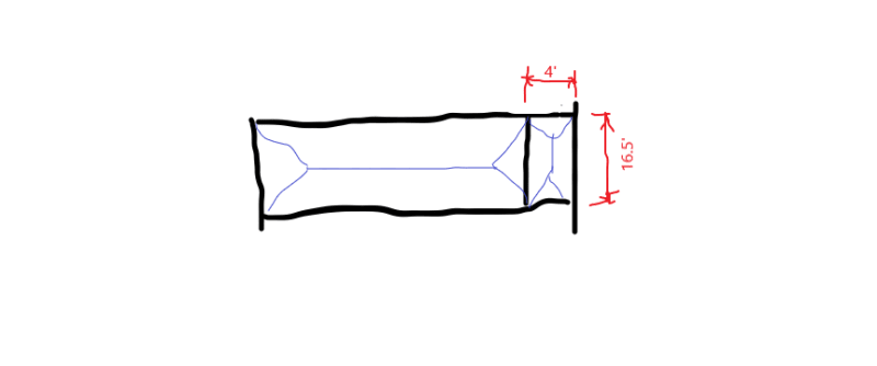
Let's have a sanity check on the 10" beam load, using the weigh you provided earlier w = 40+75 = 115 psf.

FA_aykonf.png


Calculate areas tributary to the beams:

A[sub]left[/sub] = 0.5*16.5*(16.5/2) = 68 sf
A[sub]right[/sub] = 0.5*4*16.5 = 33 sf
A[sub]trib[/sub] = 68+33 = 101 sf
Beam load = 115*101 = 11615 lbs/2 beams = 5807.5 lbs/beam
Convert to uniform linear load w = beam load/beam length = 5807.5/16.5 = 352 plf/beam

Is this what you got? Or there is mistake in my calculation?
 
Slightly. And probably a bit more useful for the pre-calculator days. That comes out to 0.3" for a 24' beam rather than the 0.288" you get from a 1/1000. You'd have to hold you laser really straight to notice the difference.
 
Retired13 ... I, admittedly, and not good at following along with someone's calculations. But let me do your sanity check a different way...

3rd floor load 115 psf
Trib span of floor to north wall = 10'
distributed load on beams = 115 psf * 10'-2" = 1150 lbs/ft

4th floor load 115 psf
Trib span of floor to north wall = 10'
distributed load on beams = 115 psf * 10'-2" = 1150 lbs/ft

Total load on beams = 2,300 lbs /ft
Divided by 2 beams = 1150 lbs / ft
 
pittguy12 - I assume you also have the self-weight of the wall included in your calculations as well in addition to the 1150 plf you show above.

 
oittguy12,

I see where I got it wrong, I was thinking about the 2nd floor only. In this sense, the 18" beam at the 2nd floor may not fare very well either. Have you checked one to see if it works?
 
JAE - In my actual calculations, yes...that has been included. But this was just a check of the floor load to show how strange even just this weight was when compared with the allowable lb/ft load in the Carnegie manual.

Retired - Yes, the 18" beams are showing the same level of overstress as the 10" beams. It is also proportional...which is comforting because its consistent with the 10" thus maybe I've computed things correctly haha...but also just as confusing.

 
Yes, confusing. By a quick calculation, assuming Fb = 18 ksi, and Sx = 25 in[sup]3[/sup], I got an allowable uniform load of 1.1 klf per beam, not very impressive compared to the loads you have :) (For 20' wall height, assume a unit weight of 120 psf, you got 1.2 klf/beam, then the 1.15 klf of floor loads above, and 0.35 klf of the 2nd floor load, a total of 2.7 klf)
 
Retired...I agree. And 1.1 klf is very close to the published allowable as well. But it is all just very odd.

For any still following it, after discussing it with the owner and explaining the shortcoming of my assessment and the possible need to engage in further select demo, material testing, etc to reach a more substantial conclusion, we have agreed to wrap up this phase of the report with a 'if we ever look to change occupancy maybe we will talk again'. In the time I've been doing this, they received an offer to sell the building so I think are just fine letting the next owner deal with it. My report will become part of the sales agreement with the caveat that more testing is needed.

But I am in sincere appreciation of the the sounding board this group has offered!
 
Sad to see the "once a life time" puzzle slip away. But I think that's maybe the best choice for everybody directly involved.

But I still think there are hidden framing inside of the masonry work that we couldn't see through. I did a quick calculation to prove the duel beams can support one story height of wall, and its own floor weight. Here is:

Assume 12' wall height @ 120 psf, w[sub]w[/sub] = 120*12 = 1440 plf/2 beams
Tributary floor load (calculated before), w[sub]fl[/sub] = 350 plf/beam
Load on one beam, w = w[sub]w[/sub]+w[sub]fl[/sub] = (1440/2)+350 = 1070 klf/beam ≅ Fb = 1100 klf allowable load calculated before.

This calculation implies there are structural beams under the roof and the 3rd floor, and there are columns (aligned with the 18" beams) to carry the beam loads directly to the foundation. So the duel beams only carries the 2nd floor wall weight and floor load. Make sense?

Hope this can help a little on your final report. Good luck.
 
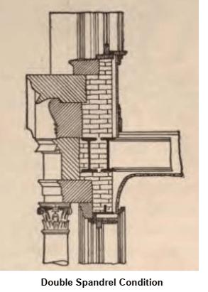
FWIW, this morning I was watching a webinar on antiquated building systems, the speaker mentioned the double spandrel. One supports the floor and the other supports the wall.

x_urlct7.png
 
Very informative and interesting.
 
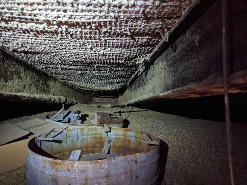
Since this popped back up and I'm seeing it for the first time, I just wanna chime in saying I love how I can find buildings using the same framing system from 100 years ago over 800 miles away. These too are "steel lumber" back to back channels
IMG_20191209_132446_qalzql.jpg
 
Draped mesh, yes, it looked and felt like it. Floor, no. This was attic space with flat roof above. I don't know why it would be use for a roof. The age, 1921, matches with pittguy's handbook.
 
I saw a draped mesh roof on a building constructed in 1960. The building is owned by my parish and the pastor wanted to knock out some walls to create a large space. I went up into the attic to check things out; first time I saw that type of roof deck. I might have a photo somewhere.
 
Status
Not open for further replies.

Part and Inventory Search

Sponsor