Continue to Site

Eng-Tips is the largest engineering community on the Internet

Intelligent Work Forums for Engineering Professionals

  • Congratulations KootK on being selected by the Eng-Tips community for having the most helpful posts in the forums last week. Way to Go!

Structural component of a beam system 2

Status
Not open for further replies.

PJMechanicalEng

Student
Nov 17, 2023
16
Hello, I need some help about this project. I need to calculate the internal forces and moment, normal stress and shear stress in the 0-45-90 strain gauge and for the linear strain gauge. However, I have doubts, especially how to calculating the shear stress and whether the internal forces are correct.
So i could make a mohr circle with the corret values. Thanks.
 
 https://files.engineering.com/getfile.aspx?folder=4e303d69-743a-42ca-8d51-374b18d7a338&file=Structural_Component_Beam_System.jpg
Replies continue below

Recommended for you

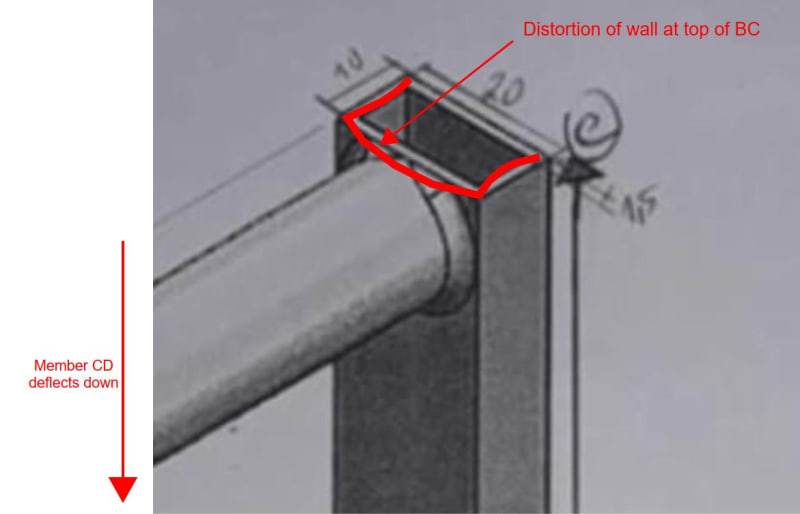
I agree dik. It's a terrible detail. I'm not sure if it was the students or the teacher who chose that detail.

Capture_vcemkc.jpg
 
Maybe a 1/4" BAR across the face welded to the sides...

-----*****-----
So strange to see the singularity approaching while the entire planet is rapidly turning into a hellscape. -John Coates

-Dik
 
is that maybe the point of the exercise ? that assuming a fixed end is maybe unrealistic ? that the assumption leads to incorrect results (compared with the test), and maybe at this level (we don't know what year at uni this is) maybe the point is to realise this, and to determine that realistically small rotations are enough to correct the results.

When you modelled the structure did you use 1D elements (BEAMs) or did you model the tube walls (as shells) ? Did you model with "large displacements" and "non-linear geometry" ?? (probably not)
A simple 1D element model should be closer to the hand calc ...

Already, we "know" from the test results that the deflections of D are non-linear.

"Hoffen wir mal, dass alles gut geht !"
General Paulus, Nov 1942, outside Stalingrad after the launch of Operation Uranus.
 
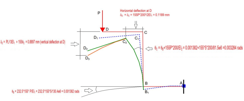
BA do you agree with this ? In the horizontal defletion SD=SC=155P*200^2/2E1 why is E1 It shouldn't be E2?

In the vertical defletion the term PL^3/3E1=5*310^3/(3*130.4e6) could you explain?

Rb1957 it is a simple 3D part on solidworks.

Thanks

Deslocamento_oycnkt.png
 
"it is a simple 3D part on solidworks." ... does this mean you modelled with 3D solid elements ? "surely" not ?? Again, I suspect you used 1D BEAM elements.

I'm pretty sure you didn't account for the flexibilities of the structure (as we're pointing out) by using non-linear geometry and large deflections; and instead ran a simple linear elastic FEM.

"Hoffen wir mal, dass alles gut geht !"
General Paulus, Nov 1942, outside Stalingrad after the launch of Operation Uranus.
 
PJM said:
BA do you agree with this ? In the horizontal deflection SD=SC=155P*200^2/2E1 why is E1 It shouldn't be E2? Yes indeed! Good catch!

In the vertical defletion the term PL^3/3E1=5*310^3/(3*130.4e6) could you explain? Yes. That is the cantilever deflection of a beam with span of 310mm and stiffness of EI[sub]1[/sub]. In addition to that, are the effects of theta B and theta C which, at the time of writing, could not include an expression for joint rotation. Since then, I have been toying with expressions to include an approximation to account for the flexibility of Joints B and C but so far, have not been entirely satisfied with the result. Unfortunately, I am not well versed in Finite Element Methods probably more familiar to mechanical engineers.
 
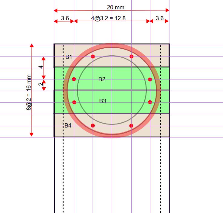
It's getting late and I'm bushed. I thought I would tackle the stiffness of Joints B and C using beams B1 to B4 as shown below. The thick red circle represents weld metal. Each beam is 4x1.5mm in cross section and is continuous around the corner of the hollow section. The red dots are loads from the circular section carried be each beam. B1 and B2 carry the same load as B3 and B4, but in the opposite direction.

I tried to use Yield Line Theory, but couldn't seem to come up with a believable arrangement of yield lines. If you have a program which can analyze these loads, let me know, because I don't particularly want to spend a lot of time developing a solution which will not be used. Otherwise, I will have a go at it tomorrow.

Capture_reqxo7.jpg
 
hey BA, I think you're going way beyond what a school project would ask for. I'd let it rest until the OP responds.

OP ...
1) do you understand what BA is doing (and how much work it is) ?
2) do you think the project would expect you to know "yield line" theory ?
3) do you know what it means ? Could you do the analysis BA is doing ? do you think the tutor marking your work will think it is your own work ?
4) what year in uni is this for ?
5) could the point of the lab be to appreciate that the results are non-linear, and to think of where non-linearities would come from ?
6) can you share the assignment ?
7) please elaborate on your FEM. How would your FEM produce non-linear results ?

"Hoffen wir mal, dass alles gut geht !"
General Paulus, Nov 1942, outside Stalingrad after the launch of Operation Uranus.
 
Rb1957 is right, don't waste any more time, as such a complex and difficult-to-understand analysis, will not be necessary for this work wich is a simple school projet, but it was already possible anyway for learning how structures work and other solutions such as the Moment Area method and the Conjugate Beam method.

Thanks
 
rb1957 said:
hey BA, I think you're going way beyond what a school project would ask for. I'd let it rest until the OP responds.

Yes rb1957, I think you are giving me some good advice.

JPMechanical said:
Rb1957 is right, don't waste any more time, as such a complex and difficult-to-understand analysis, will not be necessary for this work wich is a simple school projet, thank you anyway for learning how structures work and other solutions such as the Moment Area method and the Conjugate Beam method.

Thanks

You're welcome, JPM. I still think there was a solution, but I have not found it. It would have been a simple school project if member BC was either a 20x10mm solid bar with AB and CD butt welded to it or a circular tube mitered to fit AB and CD. That would have been a piece of cake. The 1.5mm wall was a killer.
 
It's old stuff, but I enjoy the thread and the comments. Keep 'er up BART...

-----*****-----
So strange to see the singularity approaching while the entire planet is rapidly turning into a hellscape. -John Coates

-Dik
 
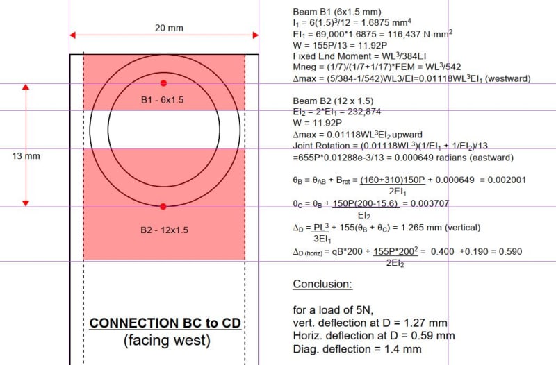
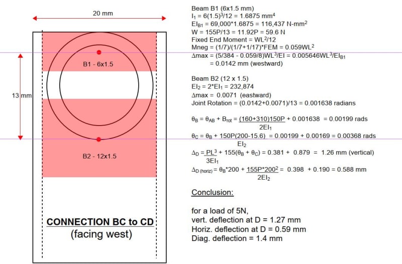
Shown below is a sketch of the connection at Joint C. Joint B is presumed to be similar. The deflection at Point D appears to be in reasonable agreement with measured deflections when the Joint rotations at Joints B and C are included.

Capture_njcsht.jpg
 
WOW ! ... measured deflection (for 5N) 1.49mm !! WOW ...

but is this effect non-linear ?

"Hoffen wir mal, dass alles gut geht !"
General Paulus, Nov 1942, outside Stalingrad after the launch of Operation Uranus.
 
It should be linear until the tube wall develops stresses above the yield point, which does not require a very high applied load. I suspect that when P exceeds 20 or 30 N, non-linearity would start to show up.

The lesson to be learned by this experiment is that tying into the wall of an HSS does not always develop the full strength of the HSS.
 
yeah, bad design = bad outcomes !

but the test showed a significant amount of non-linearity ? Nah, now I check things it isn't that non-linear, and a best fit line would work well enough.
Yes, it should be linear until things start to yield.

"Hoffen wir mal, dass alles gut geht !"
General Paulus, Nov 1942, outside Stalingrad after the launch of Operation Uranus.
 
I noticed some errors in my last post. Please ignore it and refer to this post instead.

Capture_wlau6d.jpg
 
Status
Not open for further replies.

Part and Inventory Search

Sponsor