Continue to Site

Eng-Tips is the largest engineering community on the Internet

Intelligent Work Forums for Engineering Professionals

  • Congratulations KootK on being selected by the Eng-Tips community for having the most helpful posts in the forums last week. Way to Go!

Structural component of a beam system 2

Status
Not open for further replies.

PJMechanicalEng

Student
Nov 17, 2023
16
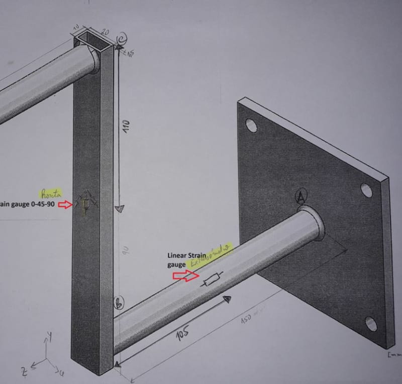
Hello, I need some help about this project. I need to calculate the internal forces and moment, normal stress and shear stress in the 0-45-90 strain gauge and for the linear strain gauge. However, I have doubts, especially how to calculating the shear stress and whether the internal forces are correct.
So i could make a mohr circle with the corret values. Thanks.
 
 https://files.engineering.com/getfile.aspx?folder=4e303d69-743a-42ca-8d51-374b18d7a338&file=Structural_Component_Beam_System.jpg
Replies continue below

Recommended for you

BAretired its aluminium alloy 6063-T6 E=69GPa

For tube AB and CD: (Do=15,6 Di=12 mm)

i'm calculating I=pi*(15.6^4-12^4)/64=1889,26 mm^4

So EI=69e9 (Pa)* 1889,26e-12 (m^4)=130.36 N.m^2

For tube BC:

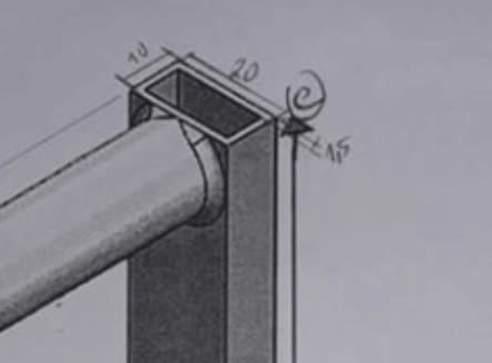
I=(20x10^3-17x7^3)/12=1180,75 mm^4 (the tube its 20x10x1,5 mm)

So EI=1180,75e-12*69e9=81,4718 N.m^2


Thanks
 
but not for BC tube (your calc for the round tube, AB and CD) ...
for BC you calc'd 1180 mm4 ?

and is E for steel defined for you ? 69000 MPa is low, 200000 MPa is typical.

"Hoffen wir mal, dass alles gut geht !"
General Paulus, Nov 1942, outside Stalingrad after the launch of Operation Uranus.
 
PJM [COLOR=#EF2929 said:
& BA[/color]]its aluminium alloy 6063-T6 E=69GPa

For tube AB and CD: (Do=15,6 Di=12 mm) I read 75.6 and 72 respectively. Your one looks like a seven to me.

i'm calculating I=pi*(15.6^4-12^4)/64=1889,26 mm^4 agreed!

So EI=69e9 (Pa)* 1889,26e-12 (m^4)=130.36 N.m^2 130.36 or 130,36 ?
I would use the decimal point, but I thought you would use a comma.

For tube BC:

I=(20x10^3-17x7^3)/12=1180,75 mm^4 (the tube its 20x10x1,5 mm) agreed

So EI=1180,75e-12*69e9=81,4718 N.m^2 agreed
 
BAretired its all corret. But i think the problem its not there.

Thanks
 
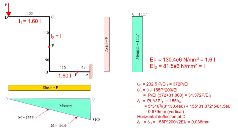
I found the vertical and horizontal deflection at D to be 0.679mm and 0.038mm respectively (see below). I haven't checked it yet, so it may contain errors, but perhaps it provides a basis for further discussion.

Capture_ojgv1j.jpg
 
Joints B and C are flexible because the circular tube is connecting to the thin face shell of the rectangular tube. Joint rotations at B and C are not included in my calculations above. They are hard to predict, and they will increase both the vertical and horizontal deflection at D.

One solution is to change member B-C from a hollow tube to a rectangular plate having equivalent strength and stiffness as the tube. Members A-B and C-D can be butt welded to B-C, and the measured deflections should be in better agreement with calculations.

bd[sup]3[/sup]/12 = 1180.75, so d = (1180.75*12/20)[sup]1/3[/sup] = 8.915mm

A plate 20x9mm could be used for B-C, if it has sufficient strength for the forces to be applied.
 
BAretired could you explain how do get 232.5 value on tetaC.

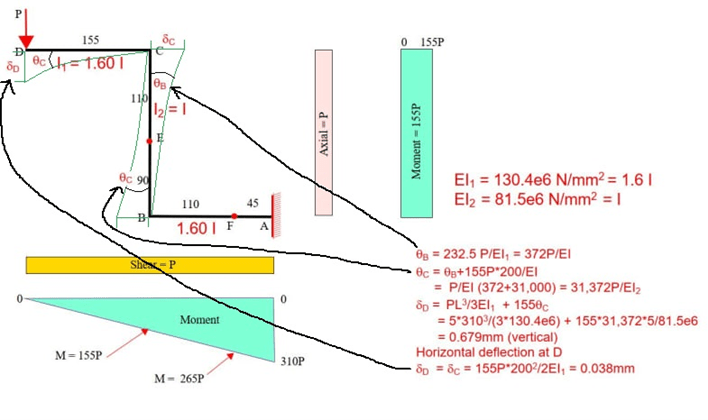
You can make a sketch of what each calculation refers to as I did in the diagram. It's hard for me to understand.

I experimentally obtained from the dial indicator a displacement for a load of 5 N of 1.491 mm and for 7 N of 1.931 mm.

My difficulty is how to arrive at a value close to these values, analytically and I don't understand how.

You say, that Joint rotations at B and C are not included in your calculations above. Do you think that you have considered, the final value would be closer to 1,491 mm to 5 N?

And the rotation at A, have you considered?
Thanks

Displacement_rdyukw.png
 
PJM [COLOR=#EF2929 said:
& BA[/color]]
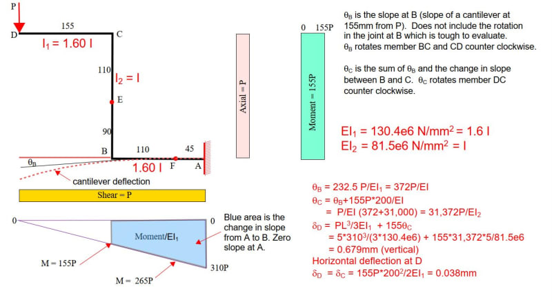
BAretired could you explain how do get 232.5 value on tetaC. Theta B, but theta C is equal to theta B plus the slope of BC. Assuming a fixed end at A, the change in slope from A to B is the area under the curvature diagram, M/EI[sub]1[/sub]. 232.5*P Is the average moment between A and B. Its area is 232.5P

You can make a sketch of what each calculation refers to as I did in the diagram. It's hard for me to understand. I'll try, but this is getting to be a lot of bloody work.

I experimentally obtained from the dial indicator a displacement for a load of 5 N of 1.491 mm and for 7 N of 1.931 mm. 1.491*7/5 = 2.09 (8% higher). So measurements can be in error.

My difficulty is how to arrive at a value close to these values, analytically and I don't understand how. No problem! You'll be an expert by the time we're done. I will try to explain in a separate post.

You say, that Joint rotations at B and C are not included in your calculations above. Do you think that you have considered, the final value would be closer to 1,491 mm to 5 N? Well, they will certainly be headed in the right direction, but I have not done the calculations yet, so cannot confirm your value.

And the rotation at A, have you considered? The rotation at A is taken as zero. I know there is no such thing as a truly fixed end, but a cantilever is normally assumed to have zero rotation at the fixed end.
Thanks You are welcome.

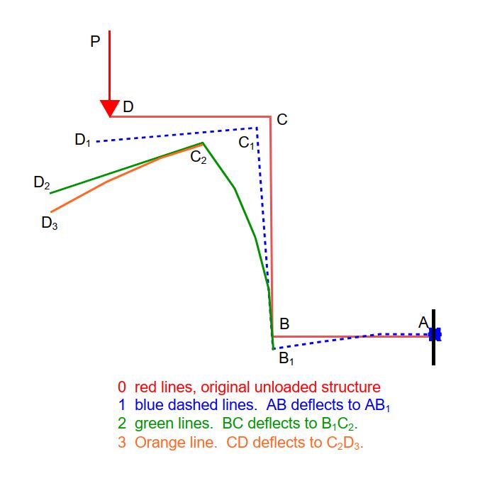
Below is a further explanation of the rotation at B and C.

Capture_hzzg8w.jpg
 
so AB deflects to an arc, so thetaB develops.
BC is fixed to the end of AB, so C rotates about B (and maybe include the compression shortening of BC since this is a school problem; yes BA, we'd probably neglect it in the real world),
and CD deflects (similar to AB)

"Hoffen wir mal, dass alles gut geht !"
General Paulus, Nov 1942, outside Stalingrad after the launch of Operation Uranus.
 
PJM said:
My difficulty is how to arrive at a value close to these values, analytically and I don't understand how.

There are several methods for finding slope and deflection. The Moment Area method and the Conjugate Beam method are easy ways of finding both slope and deflection in a straight beam, but can easily be adapted to your Z-shaped structure.

The area under the curvature diagram, i.e. M/EI diagram between any two points x1 and x2 on a straight beam turns out to be the change in slope, in radians, between those two points. Since A is the fixed end, its slope is zero, so the change in slope between A and B is also the slope at B. The area of the blue trapezoid in my last post is thetaB.

I encourage you to review the two methods I mentioned. If you're still having trouble understanding my calculations, let me know. By the way, I still have not checked my calcs, so there could be errors. They need to be thoroughly reviewed. EDIT: I think I just found an error in theta B...omitted the length 155...the fun goes on.

Joints B and C are too flexible as I have explained in an earlier post. I suggest changing member BC from a hollow tube to a solid bar with equivalent properties. It is my expectation that doing so would bring your measured results closer to the calculated values.
 
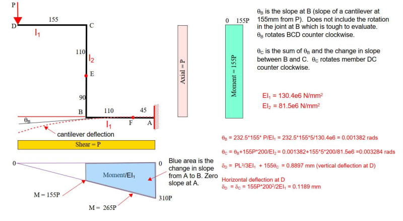
I have reviewed my file and found some numerical errors. The revised calculations follow:

Capture_aqxjcu.jpg


Hopefully these are correct, but the results are still less than the measured deflection. Stiffening Joints B and C would move us in the right direction.
 
we're dealing with such small numbers. I notice that the experimental results are quite nonlinear (worth pointing out in your lab report).

Calcs are still quite short of test results (1.49mm for 5N, 1.93mm for 7N).

I wonder what the shear deflections would work out to ? The compression shortening of BC ?

I wonder the impact of a small angular displacement at A (and B and C) ... I suspect quite large ? a 1 degree rotation at A moves D by 369*(1/57.3) = 6.4mm ! so this is the key assumption in the analysis and a small real value swamps the elastic deflection of the structure.

"Hoffen wir mal, dass alles gut geht !"
General Paulus, Nov 1942, outside Stalingrad after the launch of Operation Uranus.
 
rb1957 said:
we're dealing with such small numbers.
I agree. BC has an area of 20*10-7*17 = 81mm[sup]2[/sup]
A load of 5N puts a compressive stress of 5/81 = 0.0617N/mm[sup]2[/sup] or about 9psi, which is a very low stress, possibly not enough to measure accurately on a strain gauge.

Bending of the horizontal members AB and CD is not readily calculated either. They are welded to the 1.5mm thick wall of BC, which is going to bow inward for compression and outward for tension in the circular tube, creating a joint rotation which we can only guess at (although perhaps we could make an educated guess). Maybe a Finite Element analysis could be done to get a better idea of this effect.

Capture_uvxpp8.jpg
 
BA I was checking your calculations, however I still have some doubts about how you arrived at some equations. Can you check if the sketch I made corresponds to the displacements and slopes?

Why thetaC is the sum of thetaB and the change of slope between BC? Shouldn't be only the change of slope between BC?

In the second page i make how to get to equations of thetaB and and thetaC, could you check if looks correct?

Experimentaly i obtained for 5;7;9 [N] 1.491; 1.931 and 2.762 mm of displacement.

Now for 5 [N] a total displacement of (1.00868-1.491)/1.491 is has an error from 32.3% which is bigger than 20%

On solidworks i am obtaining a displacement on D of 0.9319 mm for 5 [N].


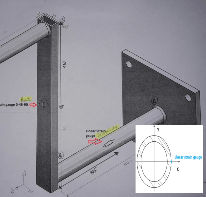
By the way rb1957, one question, if the linear strain gauge is on the x axis, analiticaly the stress sigma x=0 , wichs fits right, correponds to the -0.229 [Mpa] and -0.478 [MPa] for 5 and 7 N experimentaly obtained it is correct?
Thanks


Before we get into a discussion on numbers, let us agree on how this structure behaves. The diagram below may clear things up. Then we can look at the numbers.

Capture_y3pcxs.jpg
 
"By the way rb1957, one question, if the linear strain gauge is on the x axis, analiticaly the stress sigma x=0 , wichs fits right, correponds to the -0.229 [Mpa] and -0.478 [MPa] for 5 and 7 N experimentaly obtained it is correct?"

I don't understand why you think the s/g should read zero stress ? The top CL (where I think the linear s/g is) should be responding to the bending in the tube. Using the directions you defined in the OP, the s/g responds to Mx, but not to My ... yes ?

"Hoffen wir mal, dass alles gut geht !"
General Paulus, Nov 1942, outside Stalingrad after the launch of Operation Uranus.
 
I understand butt the linear straing gauge is on the x axis position. So responds to bending moment butt analiticaly is zero.
Mfx=265*P
Analiticaly Sigma x= (Mfx*y)/I=(265*P*y)/I)=0

The Experimental value that obtained for 5 [N] of -0.229 MPa and deformation of -3.330 us shows that is reading close to zero, wich fits right with the analitical sigmax=zero

do you agree?

Because to take experimental results i used directly hooke's law for calculating stress sigmax=Deformationx * E so for 5 [N] sigmax =-3.330e-6 x69e9=-0.229 MPa.

For the strain gauge position, in this case i dont have sigmay ,only sigmax=zero, do you agree?

Thanks

Linear_Strain_Gauge_agovdk.png
 
PJM [COLOR=#EF2929 said:
& BA[/color]]BA I was checking your calculations, however I still have some doubts about how you arrived at some equations. Can you check if the sketch I made corresponds to the displacements and slopes? It's too washed out to get a good read, but thetaC is totally wrong.

Why thetaC is the sum of thetaB and the change of slope between BC? Shouldn't be only the change of slope between BC? Why would you say that? For that to be true, member AB could not have deflected at all. When AB deflects, B goes to B[sub]1[/sub] and C moves to C[sub]1[/sub]. Then when BC deflects, C[sub]1[/sub] goes to C[sub]2[/sub] (the green line in my diagram.

In the second page i make how to get to equations of thetaB and and thetaC, could you check if looks correct? Our value for thetaB agrees. I can't read your comments about thetaC. If you want me to check any more of your stuff, type it out. I'm 90 years old and my eyes cannot take the strain of reading such terrible handwriting. It is not only bad, it is washed out...too faint to read.

Experimentaly i obtained for 5;7;9 [N] 1.491; 1.931 and 2.762 mm of displacement. Okay, I knew about the first two, but not the last result. It seems to be in fair agreement with the 5N test.

Now for 5 [N] a total displacement of (1.00868-1.491)/1.491 is has an error from 32.3% which is bigger than 20%. That is not surprising, as you are ignoring the joint rotations at B and C, and possibly A.


On solidworks i am obtaining a displacement on D of 0.9319 mm for 5 [N]. Doesn't tell me much, as I don't know what the basis was for that number.

 
ok ... very badly drawn sketch ... to be on the x-z plane it should've been on the transition from white to shade ... maybe only a small detail, but this is all we have to go by. as drawn it might be on the y-z plane (where I thought it was), or maybe at the 45 degree position. Why would you run a lab expecting a zero result ??

instead of zero you get a small stress ... ok, maybe the gauge axis isn't perfectly aligned to the AB leg ?

maybe this is the point of the lab ... how real are our idealisations (like a fixed end), how could a small reality affect the results, how could a small imperfection in the set-up (the s/g axis) affect the results ?

"Hoffen wir mal, dass alles gut geht !"
General Paulus, Nov 1942, outside Stalingrad after the launch of Operation Uranus.
 
With 1.5mm wall thickness, you will likely have great difficulty in developing the design moment in the vertical element at both the top and the bottom.

Clipboard01_o5rhhg.jpg


-----*****-----
So strange to see the singularity approaching while the entire planet is rapidly turning into a hellscape. -John Coates

-Dik
 
Status
Not open for further replies.

Part and Inventory Search

Sponsor