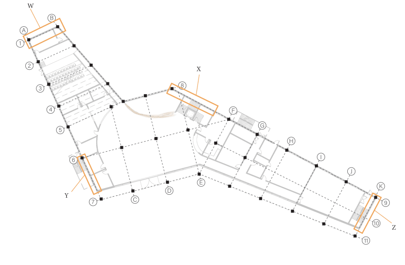
I think the structural grid is okay - but I would like to ask whether the dotted lines of the grids actually represent where beams will go or are they just to work out where to put the columns?
Grid lines are defined just as an aid or a reference point for ease in placement of structural elements during construction. It's not necessary to define grid line at every beam. Similarly, it isn't mandatory that every grid line must have a beam aligned on center.
My main question is stability...I don't think they follow the three rules I've been told:
1) Must have stability elements in each orthogonal direction
2) Must be perpendicular distance between two parallel stability elements
3) Centre of stiffness of the stability elements should be somewhere near the middle of the building
The intent of the rule no.3 is to keep the relative distance between center of mass and center of rigidity as small as possible. Large difference between the two points could result in significant torsional deformation of the building.
In fact, in one way or other, the intent of all three requirements seems to provide the most optimal mechanism to resist, or prevent the torsional mode of the building.
For example, the requirement for a pair of walls in each orthogonal direction serves dual purpose of resisting lateral force along the plane of wall plus the torsional moment due to lateral force in the perpendicular or transverse direction. The requirement for perpendicular distance between the walls is to achieve the maximum capacity to resists the twisting of the building.
Some thoughts related to your building:
Buildings with large projections and plan aspect ratios could create unwanted complexities in regards to lateral load resisting system. Therefore, it is very important for a designer to examine the best possible location to place the structural wall.
Firstly, it is difficult to provide a direct load path to transfer the lateral force from stories to the ground in a non-orthogonal building without creating points of stress concentration. Secondly, lack of symmetry in plan, in most cases, give rise to torsional mode of vibration in the earlier modes. Non circular columns are not good in resisting moment about axes other than their orthogonal axes. Therefore, the best structural system for complex shape buildings are those which would push the torsional mode of vibration to the later modes.
In addition, floor slabs in building with large aspect ratio with walls at end of the buildings only, may result in flexible diaphragm condition instead of desirable rigid diaphragm action. Providing walls between the ends of a building at certain intervals could prevent flexible diaphragm behavior. The thing with flexible diaphragm is that its in plane stiffness is almost negligible compared to the LFRS, so the diaphragm does not facilitate any interaction between frames. In addition, the distribution of lateral force to resisting elements is approximately based on the tributary area of the slab, unlike rigid diaphragm, which distribute the force in proportion to the relative stiffness of resisting elements. Thus, flexible diaphragm could result in overloading the element with less capacity.

