Eng-Tips is the largest engineering community on the Internet

Intelligent Work Forums for Engineering Professionals

Strut & Tie - Offset Column design 2

Status
Not open for further replies.

KutEng

Structural
May 27, 2019
40
0
0
AU
I have been a long time lurker on eng-tips and have finally found the need to make a post for myself.

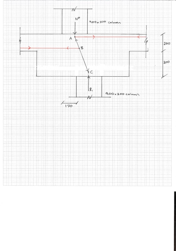
I have recently become familiar with Strut & Tie modeling and am currently faced with designing an offset column attached below. I have tried designing without a drop panel and my tie forces were far too high so added the drop panel in to increase the angle between the strut (black) and the ties (red). I know it would be ideal to have my bottom tie at node C however we do not detail reinforcement in the bottom of our drop panels at our firm.

I am wondering if my current model is reasonable (or even possible) with node B being midway through my strut. Am I missing additional struts or ties? Is this even a Strut & Tie problem or can I use standard methods of analysis? I am having trouble finding the resultant tie forces as I get different results when using the sum of all forces/moments or using simple trig so I'm assuming I am missing elements somewhere.

Any help would be greatly appreciated. Thanks.
STM_aaavph.jpg
 
Replies continue below

Recommended for you

Calvin said:
KootK, you seem to command a great deal of knowledge in this

Thanks, that's very kind of you to say.

KootK said:
..does that column strip backspan not give you any concern?

Yes, it does. And of course the magnitude of the load transferred affects the viability of the scheme (20 story vs 2 story). However:

1) I view this as something that can and should be evaluated. That's the "engineering" part of the gig, right? I reject few things out of hand based on judgment alone although this is something that's... close to being that kind of thing for me. I probably would be rejecting it out of hand were it not for #3 below. Sometimes this fact bothers me ethically but, at the end of the day, 95% of what I think I know comes from what I've learned from my colleagues and predecessors. There's really no practical way for me to separate myself from what I see as being the commonly accepted structural engineering dogma. In my opinion, the views expressed in this thread are, on average, substantially more conservative than what I've seen out in the wild.

2) In my experience, this can be made to work for a lot of common scenarios.

3) In my market, a complete unwillingness to consider this option would put me at a serious disadvantage relative to my competitors. Heck, I've got several version of standard details for this condition from some big players.

4) As I showed in my last STM sketch, the eccentricity really can be quite small in many cases and it's shared between slab left and right and column above and below for a total of four pseudo members.

5) One of the advantages of the thickening is that it spreads out the moment to a wider swath of slab. You've the 4' or so width of the thickening and then load spread out from there. You've also got a torsion mechanism on the opposite sides of the thickening but it's tough to know how to use that as we don't really reinforce for torsion directly in slab design (Wood Armer etc). You wind up engaging a fair bit of slab to resist what is a substantial load working over a relatively small lever arm.

Calvin said:
..not to mention deflection-critical.

I'm not sure that I agree with this for many practical configurations although it kind of depends on what sort of deflection you're getting at. With the columns pretty close together, it would take a crap ton of curvature to generate any serious relative displacement between columns. And any slab rotation would tend to pull the points of load delivery closer together. With columns spread out too far your would of course, start to meaningfully affect slab mid-span deflections.


I don't like to stray too far from the core ask of the OP but, in any seismic environment, two things that should be considered include:

1) Load amplification as a result of vertical seismic acceleration. And this will punish the tall, flexible buildings just as it does the short ones. And, concurrently,

2) Joint moments induced by drift compatibility with the designated lateral system.

These things will put an end to the scheme in some jurisdictions when the loads carried are heavy. They also start to push the evaluation of the scheme further towards becoming nearly intractable.

 
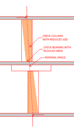
for offset columns, I always find that if possible, it is best to ensure that the area of which the two columns overlap should be designed to resist the load, although you likely do not have that luxury in this case. Trying to use the slab to resist the moment caused by offset column, as you can see clearly from KootK's S&T diagram (which I agree with), is inherently inefficient.

One of my preferred ways to transfer column is to do something like this instead:

Transfer_anjerm.png
 
Status
Not open for further replies.
Back
Top