Continue to Site

Eng-Tips is the largest engineering community on the Internet

Intelligent Work Forums for Engineering Professionals

  • Congratulations waross on being selected by the Eng-Tips community for having the most helpful posts in the forums last week. Way to Go!

Strut and tie model comprehension problem 5

Status
Not open for further replies.

Logan82

Structural
May 5, 2021
212
Hi!

Many strut and tie models in publications are not stable trusses (the members don't necessarily form triangles), yet they are accepted as is. I was wondering why?

For example, in the first picture, from ACI 318 chapter 23, the truss seems to be missing a member. I was wondering why this member was not modeled?

2021-05-05_18_54_09-ACI_318-2019.pdf_-_Adobe_Acrobat_Pro_emqfz1.png


I have added a member here to show what I mean:
2021-05-05_18_57_53-Photos_zsaaev.png
 
Replies continue below

Recommended for you

That pink member is not required to satisfy equilibrium.

Stability is satisfied simply because everything is "braced" by the large mass of concrete. How could a beam like that form a mechanism?
 
You can add the pink strut if you want (and another, and another, and another) but it’s not necessary for stability in a monolithic mass of concrete.
 
Thank you for your answers gusmurr and Tomfh. This explains the reason why they are not all triangular trusses.

I believe this beam would not have a failure mechanism with its "bracing".

The previous example was easy to calculate. However, would it be better to model complex strut and tie models as triangular trusses to calculate the load in them using a FEM software such as Advance Design America? Could it give a similar result by calculating this unstable truss using a FEM software with fixed nodes instead of pinned nodes?
 
I would avoid using fixed nodes to try to stabilised the truss model, unless you actually verify that there is negligible bending moment transmitted through the joints.

I think the usual way of getting around this stability problem is by introducing dummy members (like the pink one you showed above) with very, very small axial stiffness so that it attracts negligible load but still stabilises the truss.
 
Thank you for your answers gusmurr!
 
gusmurr said:
Stability is satisfied simply because everything is "braced" by the large mass of concrete.

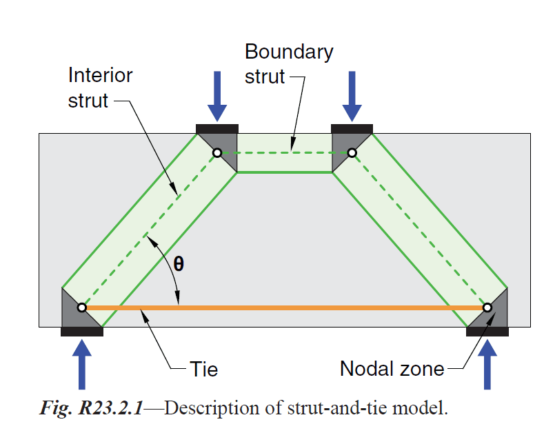
While it may feel more intellectually satisfying to add in the diagonal, I feel that gusmurr's comment above is the fundamental truth of the matter. The strut and tie method is a truss analogy and, like most analogies, it's imperfect. And perfect triangulation / explicit stability is one several ways in which it is imperfect. I believe that the stability of a model like this, put into equilibrium, is justified as follows:

1) Bracing loads for systems in equilibrium tend to be very small relative to the applied load.

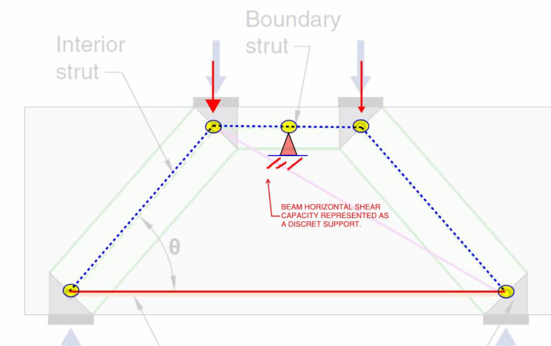
2) It's really the horizontal shear capacity of the beam stabilizing our fictional truss. and that capacity can be expected to be massive.

Were one to remove all of the concrete other than that included in the STM model, there would indeed be a problem and, most likley, a need for something like the diagonal.

Agent666 said:
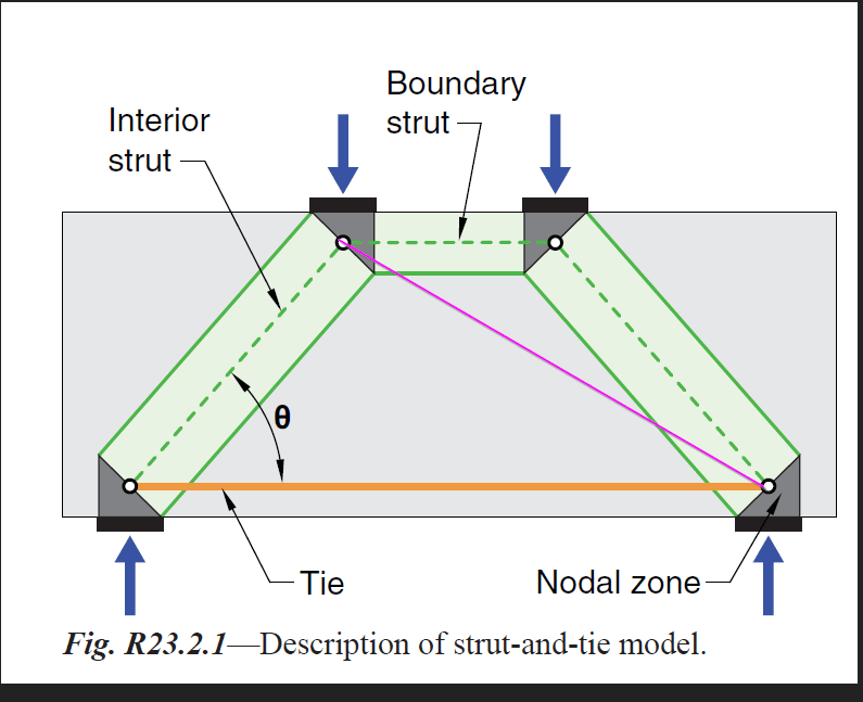
If the applied loads aren't equal then you'll need the additional diagonal won't you?

Certainly, 
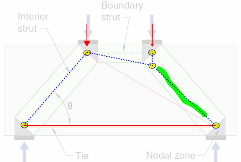
something must be done to put the model into static equilibrium. And adding the diagonal is one way to do that. Another way, I believe, is shown below. I see a couple of advantages with that approach.

1) A simpler model that might be a bit easier to prosecute at the nodes.

2) You'd not bump up against, potentially, a diagonal strut that would trigger too shallow of a strut angle (25 deg etc) in a way that may be spurious.

3) Taken in aggregate, the diagonal and the model below both capture the same, fundamental aspect of the stress field: the strut highlighted in green gets shallower.

C01_h0njm6.jpg
 
"Certainly, something must be done to put the model into static equilibrium." ... if you consider as a classical truss (with pinned joints).

But with fixed joints it is stable, and "surely" this is the understood modelling ?

another day in paradise, or is paradise one day closer ?
 
rb1957 said:
But with fixed joints it is stable, and "surely" this is the understood modelling ?

I don't believe that to be the case rb1957. Normal rebar detailing in the joints would not support rigidity and I've yet to see anything in the literature to suggest a tacit consideration of such rigidity.
 
"fixed joints" should have been more accurately expressed as "moment capable" (ie some level of fixity, not necessarily fully fixed).

If you don't have Any moment capacity in the joints (truly pinned joints) then you have no structure.

another day in paradise, or is paradise one day closer ?
 
rb1957 said:
"fixed joints" should have been more accurately expressed as "moment capable" (ie some level of fixity, not necessarily fully fixed).

I understood that in your initial comment. It's why I replaced "fixed" with "rigid" in by stuff. I don't much care which term is used as I understand the intent of both but I know that some folks here do get excited about precision in this arena.

rb1957 said:
If you don't have Any moment capacity in the joints (truly pinned joints) then you have no structure.

I disagree with that assertion. You have this:

gussmur said:
Stability is satisfied simply because everything is "braced" by the large mass of concrete.

KootK said:
It's really the horizontal shear capacity of the beam stabilizing our fictional truss. and that capacity can be expected to be massive.

Although we use a truss analogy in our STM analysis, we have to recognize that the final product here is not a truss.

Philosophically, strut and tie analyses really have more to do with capturing arching behavior than they do "trussing" behavior. The truss model is just an analytical device, it's not the whole truth of the situation.


If we're going to fixate on the truss model to the exclusion of all else, I suppose that one could represent it this way.

C01_ylgjy8.jpg
 
well, that was the original question, no ? "why is this truss considered stable ?"

The picture shows a very specific (very ideal) loading, and in this case the truss is good (with/without moment capable joints).
And doesn't need the additional diagonal member suggested.

To push the truss and say "what if it is loaded by only one load ?" or "what if one corner moves relative to the other?" isn't what the pic is trying to show.
I'm sure these cases are dealt with in other sections of your standards.

another day in paradise, or is paradise one day closer ?
 
Given that dead symmetrical loading is an utterly realistic expectation in the wild, I feel that a little digression into asymmetric loading is germane to the discussion. One might even view the asymmetrical loading as one of the possible perturbations that would induce instability.

There was never any suggestion that one corner moves relative to the other. That's just an adjustment to the analytical model to accommodate load asymmetry while still maintaining equilibrium.
 
Somebody may have already said it/alluded to it.....but is that top boundary strut even needed? Seems like a lot of S&T models I've seen handle multiple point loads without it. (Depending on the geometry.)
 
Thank you KootK and rb1957 for the replies.

WARose, I think the top boundary strut is important in the model since this strut represents a high compression zone (top flange of the beam).
 
WARose said:
Somebody may have already said it/alluded to it.....but is that top boundary strut even needed?

Are you suggesting something like the model shown below instead? Certainly, for short shear span like this, I could see that having legs.

I believe that it is frowned upon to have crossing compression struts although, frankly, I've not fully understood why that should be other that the analytical complexity that it introduces. Has anybody seen examples of crossing compression struts in the literature?

C01_mfkpdd.jpg
 
I see stuff like this too but assume that there is a boundary strut implied if not explicitly acknowledged in the sketch.

C01_wp8ww9.jpg
 
Are you suggesting something like the model shown below instead?

Yep.

I believe that it is frowned upon to have crossing compression struts although, frankly, I've not fully understood why that should be other that the analytical complexity that it introduces. Has anybody seen examples of crossing compression struts in the literature?

I'm not sure I have. But depending on the geometry, I'm not sure you'd need it. See this pic from ACI 318-11 (Fig. RA.1.2 (b)):


 https://files.engineering.com/getfile.aspx?folder=eacf9aa1-623c-4aab-8994-e944fd1eaa34&file=5.6.21.jpg
Status
Not open for further replies.

Part and Inventory Search

Sponsor