Continue to Site

Eng-Tips is the largest engineering community on the Internet

Intelligent Work Forums for Engineering Professionals

  • Congratulations waross on being selected by the Eng-Tips community for having the most helpful posts in the forums last week. Way to Go!

Strut and tie model comprehension problem 5

Status
Not open for further replies.

Logan82

Structural
May 5, 2021
212
Hi!

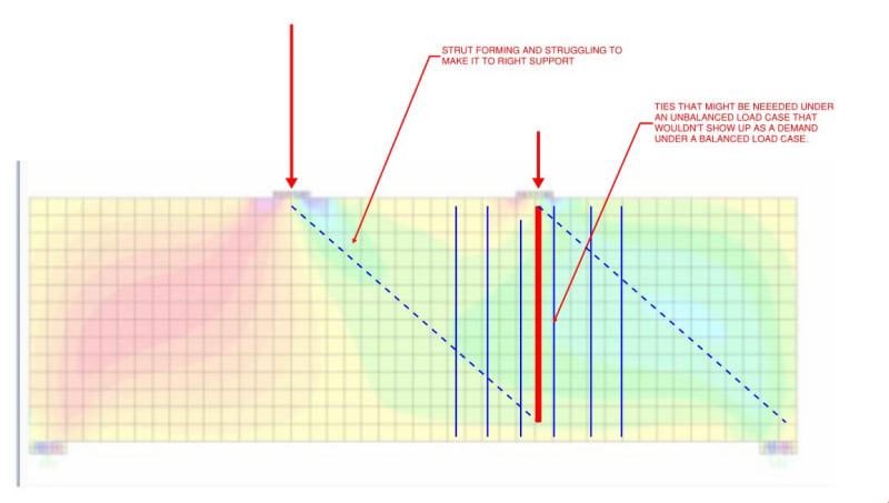
Many strut and tie models in publications are not stable trusses (the members don't necessarily form triangles), yet they are accepted as is. I was wondering why?

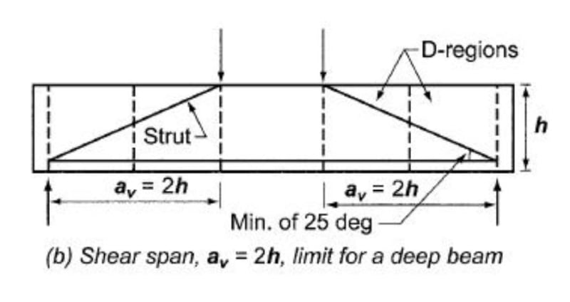
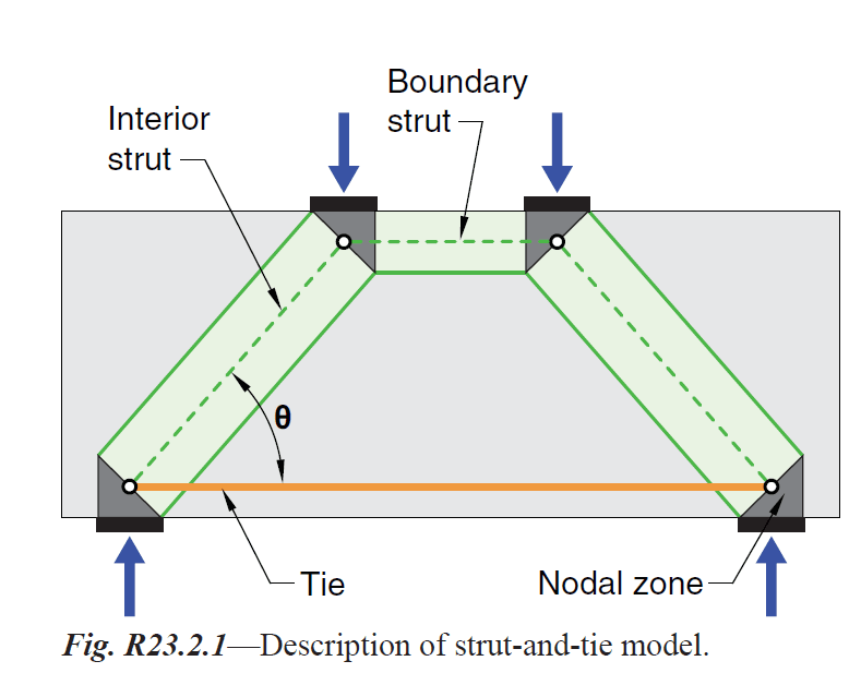
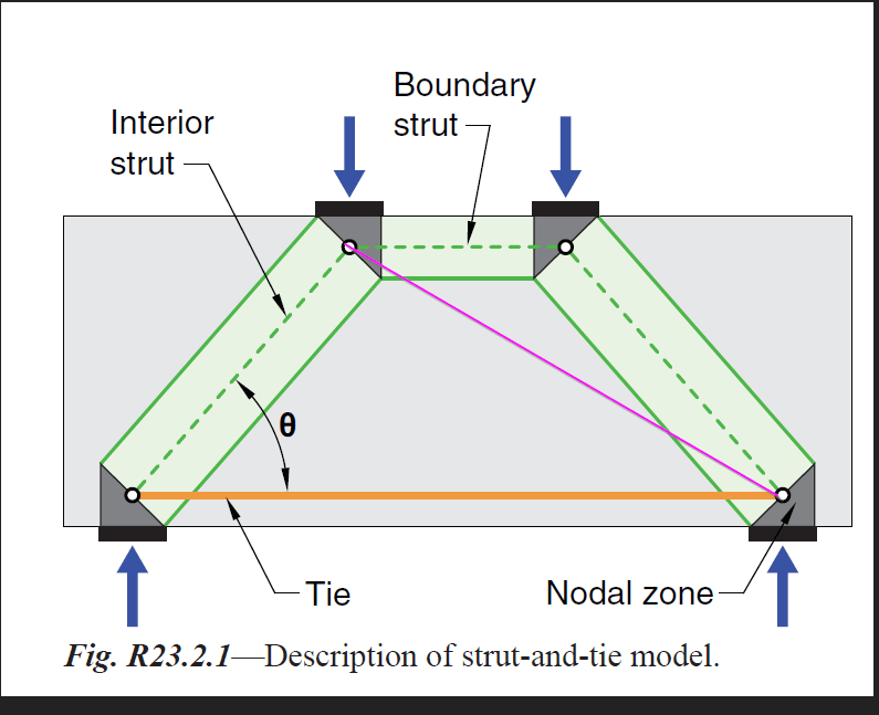
For example, in the first picture, from ACI 318 chapter 23, the truss seems to be missing a member. I was wondering why this member was not modeled?

2021-05-05_18_54_09-ACI_318-2019.pdf_-_Adobe_Acrobat_Pro_emqfz1.png


I have added a member here to show what I mean:
2021-05-05_18_57_53-Photos_zsaaev.png
 
Replies continue below

Recommended for you

Are you under the impression that there is no boundary strut in the model shown below? Or is your point that the boundary strut is really just the flexural compression block?

C01_tywe2p.jpg
 
I would have thought that with overlapping struts, you would at least have to assess the overlapped region in the same way you'd check a node.

In fact I believe it's always possible to rejig the model to introduce two adjacent triangular nodes in the rectangular overlap region, which is more in accordance with how the standards like STM to be done.
 
I think we need to look at how the forces can actually be developed and the different load cases that are involved. Remember, no matter how we want to imagine forces developing, they will initially develop in the way the concrete wants to carry them, and that is controlled by the relative strains in the concrete on different load paths.

- For the purely vertical load case with 2 point loads, the boundary strut will develop because its length is much shorter than the diagonal strut to the far column. So the concrete shortening to develop it is much less. Once it develops and compresses and shortens there will probably be a secondary much more lightly stressed diagonal strut to the far column. But is that critical? No, so we just do the 2 interior struts plus the boundary strut. As gusmurr suggests, the bulk concrete between the struts will provide any bracing required and the forces will be relatively small. The normal vertical and horizontal side face reinforcement should handle it.

I doubt it is possible to get the 2 diagonal struts to the far columns without a boundary strut in Koots later post unless the point loads are very well separated so the boundary strut is very long, in which case not much of the load is going through the long diagonal struts anyway as most of the load will go through the short relatively steep interior struts to their nearest supports.

- But a good design will allow for somewhere between 1.5 and 5% of the vertical load as a horizontal load as well. In one direction at a time. So then we have the 2 interior struts plus the boundary strut + the pink strut in the original post for sway in each direction separately.

- If there is a possibility that the loads can be applied individually then that case must be considered separately.

- If there is a possibility that one load can be fully applied and one partially (sway case or pattern live load) then the pink diagonal strut needs to be included again for sway in each direction separately.
 
Are you under the impression that there is no boundary strut in the model shown below?

Doesn't appear to be one. But I see your point as far as equilibrium goes.

 
It may be that the boundary strut is omitted from explicit consideration in sketches sometimes because it just tends to not be a big deal. Usually you've already proportioned things to get a viable compression block from the get go and turning that compression block into a boundary strut is rarely where one gets stuck.
 
I have been re-reading Schlaich Schlaich et al Book recently, and in this they show linear stress plots to help designers get to the optimal STM. To continue this discussion I mocked up a an example focusing on the load case being questioned. This is a 12m span with two point loads that lead to disturbed regions. Three load cases were considered. P/P, 2P/1P and 3P/1P.

Of interest from Schlaich:
Schlaich_model_opt_ck337g.jpg


Definition:
ACI-F1_uiqj68.jpg


LC1 Stress Plots:
ACI-F2_zpkgsq.jpg


LC2: Stress Plots:
ACI-F3_lbrke2.jpg


LC3 Stress Plots:
ACI-F4_vh0rxu.jpg


I had a little time to try a STM using the defaults in a design package, so I have included them: This is not my typical use for STM, so I have to think a bit more on their defaults. Time for the real job.
ACI-F5_lxqsvf.jpg

ACI-F6_ngjw9q.jpg
 
Thanks for doing all of that investigation work Brad805. It provides me with a perfect opportunity to discuss something that I've been thinking about for a while with regard to unbalanced loads. Namely, that a failure to consider a significant imbalance has the potential to result in designers omitting important tie elements. Thankfully, most of these things tend to be heavily dead load dominated so it probably doesn't come up much. I can't say that I've ever seen an STM design example with more than one load case considered. I guess one is just supposed to be thoughtful enough to anticipate that need on their own.

C01_ffzh5r.jpg
 
At which point it starts to look like a beam designed the usual way but ignoring concrete contribution to shear capacity.

PS: the FEA model is 3:1 so isn't a deep beam according to some codes.
 
Brad805 and KootK analysis notably highlights that 1 STM model is only valid for 1 load case. Since STM models can be long to calculate, the approach could be to limit the number of STM Models while being more conservative with the load cases.

KootK said:
Are you under the impression that there is no boundary strut in the model shown below? Or is your point that the boundary strut is really just the flexural compression block?
I believe the boundary strut can be very similar to an ACI flexural compression block if you are modeling a B-region using a strut and tie model. In the first example of this thread, this a deep beam, we are in a D-region and the flexural compression block formulas of ACI do not apply.
See 2:01 of this video:
2021-05-08_01_17_33-_ikrkwz.png

2021-05-08_01_28_03-Window_o6tumi.png


gusmurr said:
I would have thought that with overlapping struts, you would at least have to assess the overlapped region in the same way you'd check a node.
You are right. Two struts crossing would imply a CCC node.
See 18:20 of this video:
2021-05-08_01_13_27-11_-_Adv._RC_Design_Lectures_-_Strut-and-Tie_Method_updated_8_3_20_-_YouTube_plmnpf.png
 
I went searching for a study on the unbalanced load question. I found one that will be of interest to those using this methodSSDB STUDY In addition to unbalance question they also considered asymmetry.
SSDB-STUDY_xj701y.jpg


Steve, there is an interesting figure in the Schlaich report from 1987. I have included it below (avail online). I agree that the span to depth of the example beam would not be a deep beam if a uniform load were applied, but considering the point loading it has disturbed regions.
Schlaich_DeepBeam_Fig5_dxoiv3.jpg
 
strut_tie_q5jdfb.jpg


If D-region cannot be designed with B-region design, then how does normal beam design work?
 
Bearing loads within the span are non-event D-regions. Loading on concrete doesn't get better than that. You can make any beam entirely D-regions with enough point loads.

I have to read the asymmetric loading test report in more detail but note that they had a premature failure which they've excluded from their analysis of the accuracy of the design method. Is real world construction and loading going to be more forgiving than a laboratory?

The tested deep beams are also the usual micro scale stuff. Pretty rare to design a beam so small in my work. I wonder whether there's a scale effect. Also limited examination of variables such as the shear reinforcement.

But fundamentally I wonder whether S&T is being used in the best way. For fairly standard things like deep beams, researchers using parametric analysis to extend existing design rules from testing would be more efficient than designers doing routine S&T. Keep it as a last resort for the design office as I'm sure errors are being made in use of the method.
 
Logan82 said:
I believe the boundary strut can be very similar to an ACI flexural compression block if you are modeling a B-region using a strut and tie model. In the first example of this thread, this a deep beam, we are in a D-region and the flexural compression block formulas of ACI do not apply.

Thanks for the clarification Logan82, I agree. That said, you'll note that I took care to not use the terms ACI Compression Block or Whitney Compression Block. Rather, I just went with Flexural Compression Block. And I contend that there is a flexural compression block in all situations. The only question is that of what the appropriate treatment of that compression zone is for a particular case being considered:

1) Whitney/ACI stress block for Bernoulli regions.

2) Boundary struts for disturbed regions.

3) The old school lever arm method that I use regularly (steveh49's point regarding simplified methods).

The notion that a deep beam isn't so flexurally deep after all is really what got the whole consideration of arching/STM rolling in the first place. It's a lesson that I've not forgotten since first learning it, I assure you.

c02_dnzsa1.jpg
 
steveh49 said:
But fundamentally I wonder whether S&T is being used in the best way. For fairly standard things like deep beams, researchers using parametric analysis to extend existing design rules from testing would be more efficient than designers doing routine S&T. Keep it as a last resort for the design office as I'm sure errors are being made in use of the method.
What calculation method do you suggest using for the D-regions instead of the Strut and Tie Method, such as for instance the corbels and moment resistant connections?

Interesting figure KootK regarding the flexural stresses in a deep beam.

KootK said:
3) The old school lever arm method that I use regularly (steveh49's point regarding simplified methods).
What is the method you are referring to?
 
I know it as "The Reduced Lever Arm Method" from Park & Paulay"s tome on reinforced concrete.
 
Instead of opening another thread let me ask a strut and tie question here. I have been studying the method for some weeks now and I was wondering about something.
Lets suppose you have an STM for a deep beam like the one on Brad805's post or rather you have two. The first with the tie and the second without.

1. On a model with a tie, you design the reinforcement according to the tie and according to the bursting force of the struts on each side of the tie, correct? Meaning, would the vertical reinforcement be additive of the two or the maximum of the two?

2. Continuing from before, lets say the width of the beam is significant, any shear reinforcement (tie) would have to span the whole width according the minimum stirrup leg distances. On the other hand, the orthogonal mesh of the bursting reinforcement is put on each face of the deep beam. My question is, if the above are true and you want to compare the reinforcement of the two models described above (one with tie+bursting and one without i.e. only bursting) wouldn't the comparisson be impossible, since with the tie you would put reinforcement in the interior of the beam also and not only on the surfaces.

I would appreciate any input! Thank you
 
Status
Not open for further replies.

Part and Inventory Search

Sponsor