Continue to Site

Eng-Tips is the largest engineering community on the Internet

Intelligent Work Forums for Engineering Professionals

  • Congratulations SSS148 on being selected by the Eng-Tips community for having the most helpful posts in the forums last week. Way to Go!

Strut and tie model 1

Status
Not open for further replies.

WARose

Structural
Mar 17, 2011
5,594
First off, let me tell you: I’m not the most knowledgeable guy when it comes to strut and tie models. Hardly ever used them. (So pardon the novice questions here.)

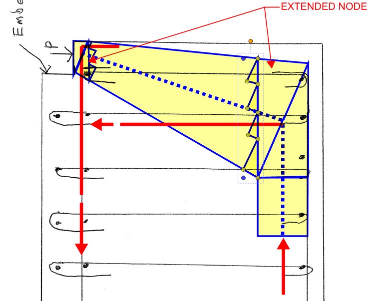
My problem: I have something I am modeling with a strut and tie model. At least one “node” here will be a “C-T-T” node. (See Fig. RA.1.7 in ACI 318-11.)

My question is this: if I develop all the forces at the node properly……and the system (as a whole) is in equilibrium (i.e. the concrete can take the forces developed…….is that it? All that is required?

I ask because a lot of the strut and tie models in Appendix A “close” (for a lack of a better way to put it). A good example of that is the deep beam model they have: all the forces are connecting via nodes. I just have one node in my model.
 
Replies continue below

Recommended for you

How do you only have one node?

Can you post a sketch?
 
In general it is as straight forward as you've described, serviceability issues excepted. It's difficult to say for certain though without a greater umderstanding of your specific case. Will your tension ties pass through the joint or wrap around the joint?

One node huh... mysterious. Maybe a tension tie for some kind of anchorage device?

 
Will your tension ties pass through the joint or wrap around the joint?

Wrap around.

Maybe a tension tie for some kind of anchorage device?

Sort of. Basically a embed that puts a compressive load into the concrete that I am trying to take out.

 
For wrap around, you want bar radius large enough that you're not crushing concrete inside the bend. Goole curved bar node.

 
And, obviously, the ties should go someplace discrete as opposed to just being developed.

 
Kootk, see attached for a pic. It's basically a embed angle in a slab of concrete. The load is such that I couldn't get it to work doing it like a shear lug.....so a strut and tie was my next try. (See page #2 for the grand total of one node.)

As a alternative to the strut and tie model, I was thinking of using those stirrups (to reinforce the shear plane).....but I'm not sure I've used supplemental reinforcing placed like that for a embed like that before.
 
 https://files.engineering.com/getfile.aspx?folder=794c3984-124f-4f4f-86e7-9523158c3e66&file=model.pdf
WARose,

I don't think you've maintained static forces at that lower node. The horizontal force should be compression opposing the force coming down along the strut. For this situation, I'm seeing (2) C-C-T nodes (one at the top where the notch is, and the node shown on page 2). Drawing the FBD on the cut shows the bottom face in compression.

Capture_lk3iht.jpg
 
This is looking pretty similar to Widianto stuff to me. You might find some useful ideas there.

c01_zkcdtm.jpg
 
This is typically how S&T goes for me. I feel as though it's super simple right up until I try to execute a model that doesn't already exist in print someplace. Then I choke and defecate the bed entirely. S&T must be the worlds most complicated simple thing.

c01_cb8mxq.jpg
 
And don't worry, I don't actually expect you to follow this through. Only students have that kind of time on hand. Just some ideas.

 
Thanks Kootk. What do you think of the shear plane reinforcement idea? (In other words treat it like a lug and shear reinforce the failure plane.)
 
WARose said:
What do you think of the shear plane reinforcement idea?

I'm mostly cool with it. It is, after all, very much the same thing. And I believe that's still what's shown in the AISC base plate design guide. If you combine that with some thoughtful detailing regarding anchorage of your tension bars at the top left node, I'd think that you'd be in pretty good shape. As long as your stirrups are smallish diameter and detailed conventionally, I don't see you running into any anchorage problems at the bottom right node.

The inherent weakness of the shear plane reinforcement method was always that it didn't directly address the detailing required to keep that block of sheared concrete from rotating clockwise in space rigid body style. In days gone by, we handled that with some thoughtful detailing and a dollop of hope. Obviously, the whole thing feels a lot better if you're dumping a bunch of compression on top of the wedge as is sometimes the case for a base plate condition.

 
[blue](Kootk)[/blue]

I'm mostly cool with it. It is, after all, very much the same thing. And I believe that's still what's shown in the AISC base plate design guide. If you combine that with some thoughtful detailing regarding anchorage of your tension bars at the top left node, I'd think that you'd be in pretty good shape.

I'm kind of pressed for space there.....so anchoring like you are showing (i.e. with that added red bar with the 90 degree hook) would be tough. The way I have it sketched is about where you'd have to have it to clear that angle. Actually the first stirrup would be further back than that.

[blue](Kootk)[/blue]

The inherent weakness of the shear plane reinforcement method was always that it didn't directly address the detailing required to keep that block of sheared concrete from rotating clockwise in space rigid body style. In days gone by, we handled that with some thoughtful detailing and a dollop of hope. Obviously, the whole thing feels a lot better if you're dumping a bunch of compression on top of the wedge as is sometimes the case for a base plate condition.

Yeah, that's why I got all that top & bottom steel. I would think it could be treated like a shear friction/shear problem......but I don't have a warm, fuzzy feeling there because there isn't a stirrup directly under the angle. (Contrary to what the pic shows.) But then again, the shear cracks should intersect the stirrups.

 
Maybe some compromises on the theory will need to be made in the interest of practicality. At the least though, you need to tell some kind of story that has an FBD of the cracked wedge in static equilibrium and develops any bars being relied upon. Could you put some hooked bars in where I've shown them in red below? Lap those generously with your primary flexure bars?

WArose said:
I would think it could be treated like a shear friction/shear problem......but I don't have a warm, fuzzy feeling there

I'd be careful with that. I'm not exactly sure which plane you're proposing doing SF on but, in general, it's the case that shear friction AND diagonal tension shear need to be satisfied. Usually one can not simply be used as a substitute for a deficiency in the other.

c01_zmjtkf.jpg
 
Can I ask what the hesitation is on the S&T model? Provided you have the nodal bearing area and strut capacity, it looks pretty straightforward. If your strut is causing your problems, you can literally put an inclined, tied cage along the strut.

Otherwise, everything Koot has drawn looks like variations on the same forces/reinforcement(which, come to think of it, is probably why S&T works).

WARose, are you at liberty to share some of the dims and load magnitudes?
 
[blue](Kootk)[/blue]

Could you put some hooked bars in where I've shown them in red below? Lap those generously with your primary flexure bars?

I can take a look.

[blue](Kootk)[/blue]

I'd be careful with that. I'm not exactly sure which plane you're proposing doing SF on but, in general, it's the case that shear friction AND diagonal tension shear need to be satisfied. Usually one can not simply be used as a substitute for a deficiency in the other.

Good point. Thanks again kootk.
 
Maybe some reinforcing bar anchors welded to the angle?

Capture005_ud3ddr.png


BA
 
Status
Not open for further replies.

Part and Inventory Search

Sponsor