Hello,
I am studying the concept of strut and tie method and modelled an rc wall and try to figure out the correct truss model for the STM.
I have the following questions;
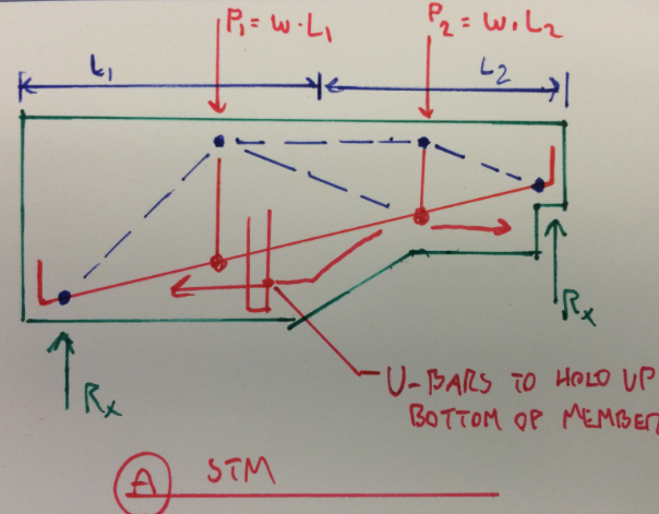
1. How do you normally size the strut? looking at some examples, if the point load is coming from the column, it is quite easy just simply relate it to the size of the column, but how about if you have a "line load", I've just converted the line load to a point load(pls. see attached.
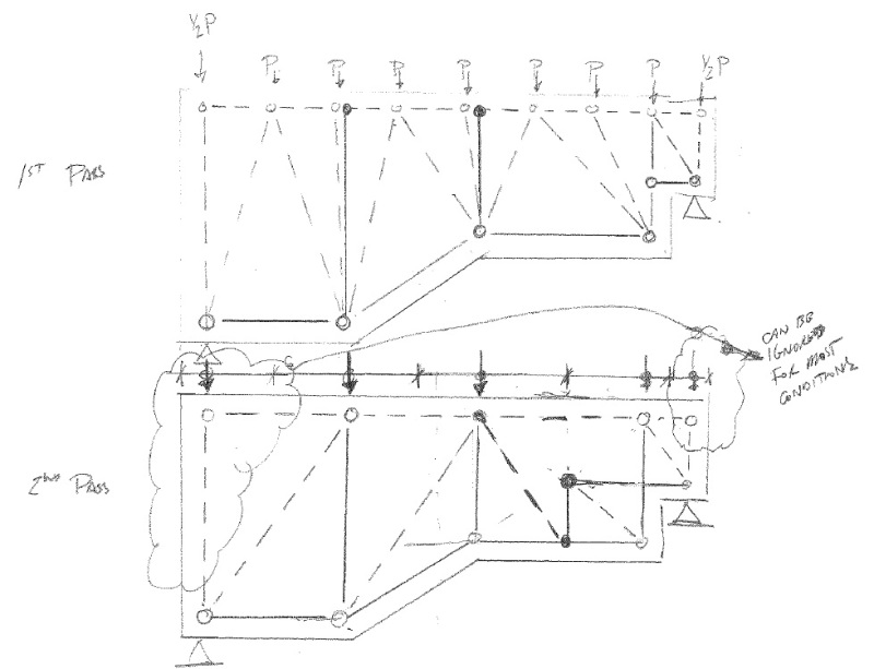
2. When you have a line load, and you intent to convert it to 2 point loads on top of the rc wall, normally, you just take half & half approach(pls. see attachment, in the line load diagram, I enclosed in "red" line load converted in to point loads). But how about the other "halves" outside the "red zone" do I need to include them as well?or just simply leave it according to my model?
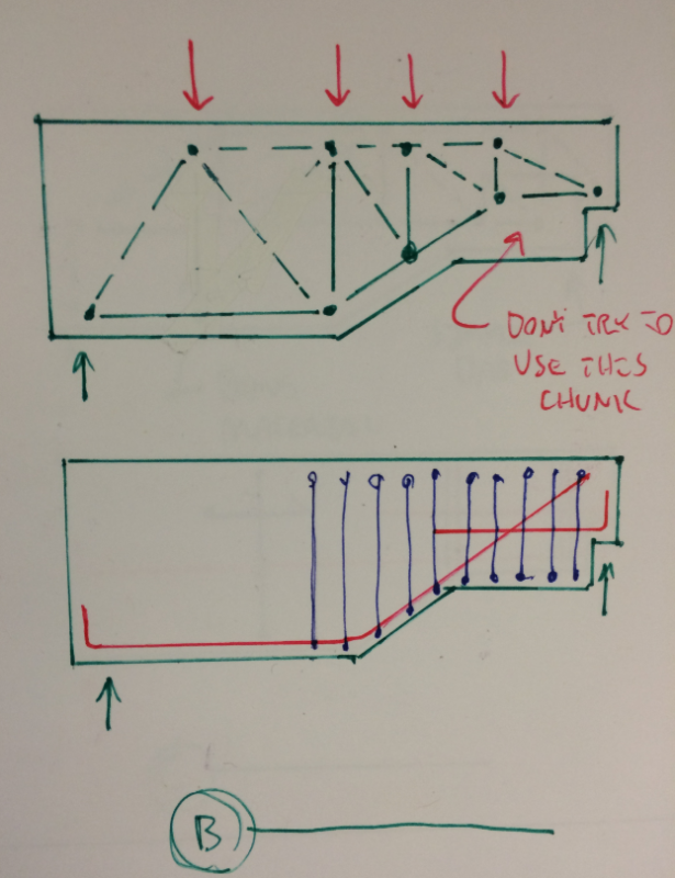
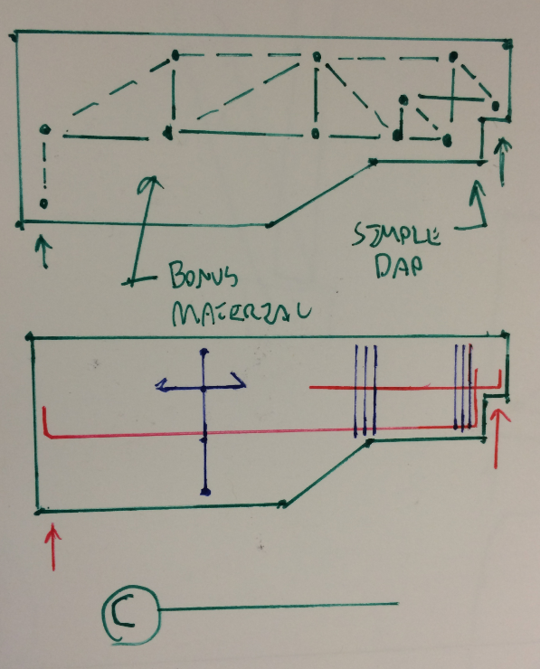
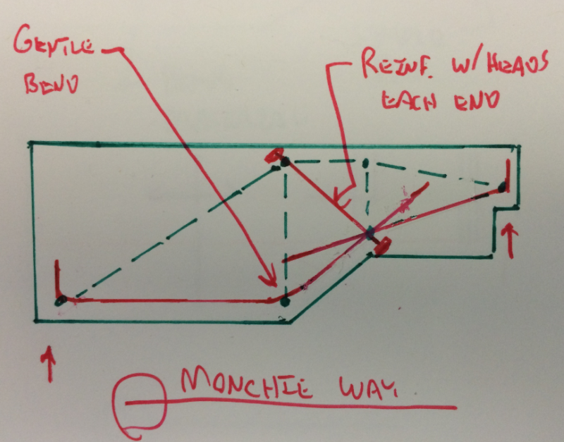
3. Based on the result that I've got(Black (Tension), Green(Comp), Red(Reactions)). How do you provide "matching" reinforcement for this?
Any ideas/suggestions are highly appreciated.
I am studying the concept of strut and tie method and modelled an rc wall and try to figure out the correct truss model for the STM.
I have the following questions;
1. How do you normally size the strut? looking at some examples, if the point load is coming from the column, it is quite easy just simply relate it to the size of the column, but how about if you have a "line load", I've just converted the line load to a point load(pls. see attached.
2. When you have a line load, and you intent to convert it to 2 point loads on top of the rc wall, normally, you just take half & half approach(pls. see attachment, in the line load diagram, I enclosed in "red" line load converted in to point loads). But how about the other "halves" outside the "red zone" do I need to include them as well?or just simply leave it according to my model?
3. Based on the result that I've got(Black (Tension), Green(Comp), Red(Reactions)). How do you provide "matching" reinforcement for this?
Any ideas/suggestions are highly appreciated.