ProbingStructuralEng_03
Structural
Hi All,
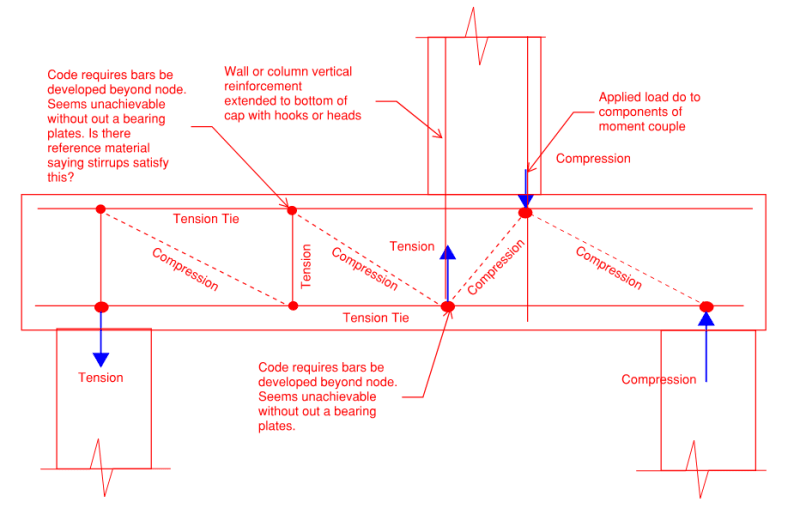
Looking for some input on how you all handle ACI requiring tension ties anchorage at nodes. ACI Section 23.8.2 states Tie reinforcement shall be anchored by mechanical devices, post tensioning anchorage devices, standard hooks or straight bar development in accordance with 23.8.3 (Tie force shall be developed in each direction at the point where the centroid of the reinforcement in the tie leaves the extended nodal zone)except for ties extending from curved-bar nodes designed in accordance with 23.10. From quick numbers I have run the curved bar node method opens a can of worms itself.
How do you guys handle the anchorage requirements of internal ties? Its easy to picture end bearing plates for horizontal ties but what about the vertical ties? I don't believe the industry is seeing internal vertical ties constantly detailed with to be anchored by bearing plates so what's the methodology here? Is it really just the curved bar node theory to satisfy the anchorage requirements? I know I have seen folks say well put stirrups in and you are good but whats the logic there?
I appreciate you input on this. Strut and Tie is one method I feel engineers constantly try to engineer judge their way out of but I think ACI has made it pretty clear its a required analysis method for so many scenarios. I just want to find a way that this is all practically
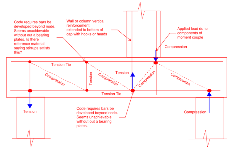
 detailed to help get every one on board. I have attached a picture of a situation I think may be a common scenario for folks. The example is essentially a wall or column supported on a a pile cap that has substantial moment that creates a tension load that needs resolved. You could even simplify this and just look at a column with a tension force in stead.

Looking for some input on how you all handle ACI requiring tension ties anchorage at nodes. ACI Section 23.8.2 states Tie reinforcement shall be anchored by mechanical devices, post tensioning anchorage devices, standard hooks or straight bar development in accordance with 23.8.3 (Tie force shall be developed in each direction at the point where the centroid of the reinforcement in the tie leaves the extended nodal zone)except for ties extending from curved-bar nodes designed in accordance with 23.10. From quick numbers I have run the curved bar node method opens a can of worms itself.
How do you guys handle the anchorage requirements of internal ties? Its easy to picture end bearing plates for horizontal ties but what about the vertical ties? I don't believe the industry is seeing internal vertical ties constantly detailed with to be anchored by bearing plates so what's the methodology here? Is it really just the curved bar node theory to satisfy the anchorage requirements? I know I have seen folks say well put stirrups in and you are good but whats the logic there?
I appreciate you input on this. Strut and Tie is one method I feel engineers constantly try to engineer judge their way out of but I think ACI has made it pretty clear its a required analysis method for so many scenarios. I just want to find a way that this is all practically


