Baek
Civil/Environmental
- Oct 19, 2015
- 14
Hello all,
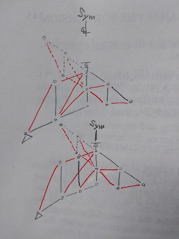
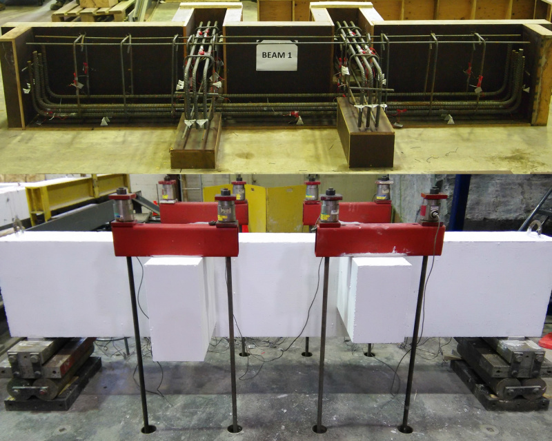
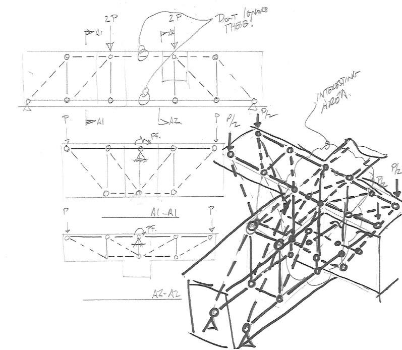
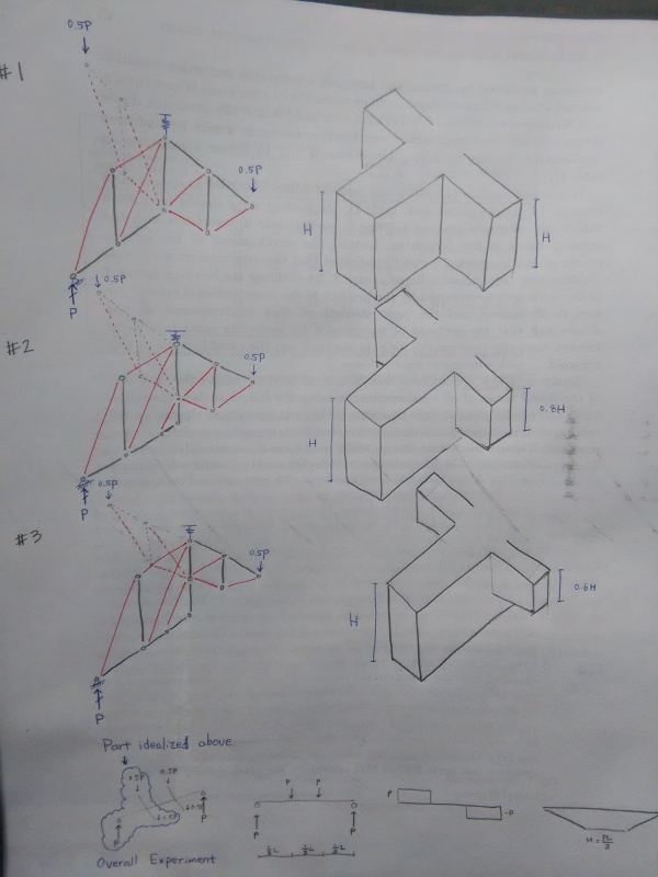
I have a sort of research to be done on strut and tie model related to reinforced concrete girder to beam joint which of monolithic cast. Here are described specimens, with a few necessary information for you to picture them. Overall test layout is simply shown below and #1, #2, and #3 are focused on showing strut and tie idealization and the only difference between specimens which is height of loading beam (BEAM). Circle is for node, black is for tension tie, red is for compression strut and dashed line is just for visual distinction of a part behind another part.
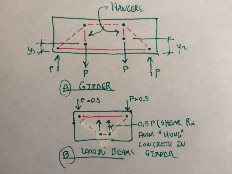
Longitudinal rebar is on the bottom of supporting beam (GIRDER) and on top of BEAM. GIRDER contains minimum stirrups with hanger reinforcement (11.2.12 of CSA A23.3-04, not required by ACI) and BEAM contains just one stirrup on each overhang, so two in a BEAM. No torsion should be induced since specimens and loads are symmetrical. Shear and bending are the only elements of external force occurring failure.
Here are my questions.
1. Should I defer inclination angle of GIRDER between specimens #1, #2 and #3, since the angle in BEAM is different? (The angle should decrease as height decreases.)
2. Is there any better idealization of specimens especially drawn parts using 3D strut-tie-model?
3. Is there any better idealization of specimens especially drawn parts other than strut-tie-model?
4. Stiffness of spring should be about 400kN/15mm according to test data, should it be modeled you think or can it be just pin for a sake of simplification?
5. What would you guess for the strongest and the weakest among 3 specimens given that inclination angle of strut in BEAM is in H>0.8H>0.6H but at the same time additional loading(11.2.12 of CSA A23.3-04) in GIRDER due to BEAM is in H>0.8H>0.6H?
Thank you for taking your time reading and look forward you to sharing technical expertise.
I have a sort of research to be done on strut and tie model related to reinforced concrete girder to beam joint which of monolithic cast. Here are described specimens, with a few necessary information for you to picture them. Overall test layout is simply shown below and #1, #2, and #3 are focused on showing strut and tie idealization and the only difference between specimens which is height of loading beam (BEAM). Circle is for node, black is for tension tie, red is for compression strut and dashed line is just for visual distinction of a part behind another part.
Longitudinal rebar is on the bottom of supporting beam (GIRDER) and on top of BEAM. GIRDER contains minimum stirrups with hanger reinforcement (11.2.12 of CSA A23.3-04, not required by ACI) and BEAM contains just one stirrup on each overhang, so two in a BEAM. No torsion should be induced since specimens and loads are symmetrical. Shear and bending are the only elements of external force occurring failure.

Here are my questions.
1. Should I defer inclination angle of GIRDER between specimens #1, #2 and #3, since the angle in BEAM is different? (The angle should decrease as height decreases.)
2. Is there any better idealization of specimens especially drawn parts using 3D strut-tie-model?
3. Is there any better idealization of specimens especially drawn parts other than strut-tie-model?
4. Stiffness of spring should be about 400kN/15mm according to test data, should it be modeled you think or can it be just pin for a sake of simplification?
5. What would you guess for the strongest and the weakest among 3 specimens given that inclination angle of strut in BEAM is in H>0.8H>0.6H but at the same time additional loading(11.2.12 of CSA A23.3-04) in GIRDER due to BEAM is in H>0.8H>0.6H?
Thank you for taking your time reading and look forward you to sharing technical expertise.

