Continue to Site

Eng-Tips is the largest engineering community on the Internet

Intelligent Work Forums for Engineering Professionals

  • Congratulations waross on being selected by the Eng-Tips community for having the most helpful posts in the forums last week. Way to Go!

Strut-Tie - Tie Development at Nodes (Starter Bars) 1

BacBac

Structural
Aug 11, 2024
19
Reviving this thread:

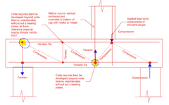
Does anyone have any ideas on how to justify the starter bars reinforcement is developed at the node?
For the shear ties, reference from Australian Standards, it's said to be fully anchored if shear ties detail is followed (AS3600-2018 clause 12.2.1 that refers back to Clause 8.3.2.4 for anchorage of shear ties).

However, nothing is referred for the development of the starter bars of the column.
Any help would be appreciated
Thanks!.
S&T Starter Bars.PNG
 
Replies continue below

Recommended for you

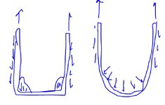
I don't get why not use a loop? It should have an instant anchorage.
Also @KootK why is the node of the same size in both sketches? Shouldn't the node on the left be smaller? I guess it depends on the whole structure, but here we're talking about the strut "hanging" on that tie. It's primarily resting on the bend in this case, is it not?
That said, I generally agree that it is better to have more small bars.
 
Also @KootK why is the node of the same size in both sketches? Shouldn't the node on the left be smaller?

No, I don't believe that it should be smaller. In my experience, node geometry is independent of bar size / hook "bigness".
It's primarily resting on the bend in this case, is it not?

Yes, and that's precisely what I don't like about it. Bends tend to... unbend. And resisting the tie force out on the bend introduces additional eccentricity.

I don't get why not use a loop? It should have an instant anchorage.

Are loops not annoying to place and keep in place during pouring?
 
No, I don't believe that it should be smaller. In my experience, node geometry is independent of bar size / hook "bigness".
How does the "increase the bend" idea work then? I was under the impression that it spread the load and reduced the stress inside a bend.
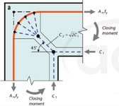
Here's a figure from ACI. If the bend is decreased the strut area decreases and stresses increase, or am I wrong?

EDIT: Sure, when you have usual dimensions there should be no difference, but the way you drew it is a huge difference in the bend radius and I feel like that causes a difference.
ACI.PNG

Bends tend to... unbend.
But you still put a bend on the smaller bar and count on it reducing the anchorage length (and causing the same eccentricity "problem"). You’re still relying on that bend to do the same thing, just to a lesser extent. For examplewe use 4D mandrel diameter, it’s 5D in the US? If I put it to 6D I’m not that far off from the US standard way of doing it, but I just increased it by 50% of my standard value. It's not like I'm talking about something that's novel, as far as I am aware this was all tested experimentally and if you follow code provisions you'll get yield before "unbending" of the bar. This unbending would also require a small enough concrete cover at the bottom, which should not be a problem for a footing. Especially since you have longitudinal bars that stop the opening of the bend.
Are loops not annoying to place and keep in place during pouring?
May be. It's deffinitely not as easy as standard hooks, but I don't think it's impossible (you should be able even to put just hairpins and splice the straight vertical bar on top).
Currently in europe if you want to make an RC coupling beam you need to make an X each with it's own ties, that's in my opinion significantly harder to do and still it is done sometimes.
 
Last edited:
How does the "increase the bend" idea work then?
I don't know that it does work in the context of the problem being discussed.
I was under the impression that it spread the load and reduced the stress inside a bend.
It does but, as you can see from the model in that ACI diagram, it also creates a significant eccentricity between the line of action of the incoming rebar and what ends up being the node. That setup "works" for the problem it was intended to solve:

1) Incoming and outgoing bar force the same.

2) A closing corner situation where the eccentricity between the effective node and the line of action of the rebar is not a problem.

I'm not saying that the curved bar node model can't be adapted to other situations. I've done that myself. That said, the further that you get from [1] and [2] the less it makes sense and the more nuance needs to be considered to make a go of it.

If the bend is decreased the strut area decreases and stresses increase, or am I wrong?

I do feel that you are wrong in this particular case. Increasing the bend diameter makes for a gentler delivery of bar stress but, as far as I know, does not change the assumed stress condition at the nodal faces.
but the way you drew it is a huge difference in the bend radius and I feel like that causes a difference.
Well... yeah. The whole reason that I drew the sketch was to make a point. And I couldn't very well make the point if the rebar size difference was barely perceptible. The point being:

1) I do not agree that a larger bar / bar bend improves anything here.

2) In many cases, I argue that a larger bar / bar bend probable makes things worse.
 
But you still put a bend on the smaller bar and count on it reducing the anchorage length (and causing the same eccentricity "problem").

Yes. But I would argue that your presentation is backwards.

It is not the case that, because small hooks are okay, large hooks are okay.

Rather, all hooks represent a problem / compromise to some degree. And, commensurately, the larger the hook, the larger the problem.

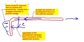
If you imagine how a hook delivers the bar tension to the surrounding concrete, there will always be an eccentricity between those stresses and the line of action of the incoming bar. And that eccentricity often is a problem in the sense that, in many cases, that is resolved via some version of relying on concrete in tension, which we generally try to avoid when possible.

Make no mistake: it is not the case that Ldh (hooked bar) is as good as Ld (straight bar). In most common situations, hooks are only tolerated as a compromise in homage to the practicalities of dealing with spatial constraints
It's deffinitely not as easy as standard hooks, but I don't think it's impossible (you should be able even to put just hairpins and splice the straight vertical bar on top).

Frankly, I don't feel that a hoop would perform all that much better than a pair of inward facing hooks. Kinda depends on the bar size and the width of the hoop trough. So I guess that I just don't see the logic in incurring the placement difficulty. Not enough gain to justify the pain.
 
1) Incoming and outgoing bar force the same.
I do not agree. Most experiments are done on a single bar pulled on one side, so the other leg has a force of 0... and still increasing the bend diameter helps.
Look at this paper for example: https://www.sciencedirect.com/scien...?ref=pdf_download&fr=RR-2&rr=8e6288f0eac7ec22
Equation 11 shows clearly that the force transferred by the bend is proportional to the mandrel diameter even when there is no tension in one of the legs.
PS. Keep in mind that this discussion is only about the bend + tail part... consider that you have exactly the same length of the first straight part and the same bar diameter.
I do feel that you are wrong in this particular case. Increasing the bend diameter makes for a gentler delivery of bar stress but, as far as I know, does not change the assumed stress condition at the nodal faces.
It does not if you look at it code-wise, a CTT node is still a CTT node. But if you look at it code-wise you can anchor it any way you want, it does not mention anything that you're talking about. So we need to talk about the actual physics. Again, look at the paper, now equation (8) and text before it. Stresses inside a bend need to be checked for the local crushing of concrete - stress is deviation stress / diameter of a bar. Is this not the crushing of a strut that is forming? Is it something else?
Now look at equation (A.16) - deviation stresses at the curved part of the bar... larger the bend diameter, smaller the deviation stresses.
In other words, larger the bend diameter is, less probable it is that concrete will crush. Since in equation (8) strength is the same it means that a diagonal strut has a different dimension. It may not be a huge difference, I don't know.
I do not agree that a larger bar / bar bend improves anything here.
Oh I never said that a larger bar is better. I'd use the smallest bar possible, but I would use a mandrel diameter of 6D and reduce the anchorage length by around 15% (based on the code) without worrying too much about it.
It is not the case that, because small hooks are okay, large hooks are okay.
We completely agree in this respect. But you chose 5D as an OK bend diameter, but if I want to make it 6D it's not OK? I agree that you need to be careful if using 20D, but a small increase should not matter and it can help. And if tomorrow code changes and says that a standard bend diameter is 6D, do you think we'd suddenly see a huge number of damaged buildings because of that?
And that eccentricity often is a problem in the sense that, in many cases, that is resolved via some version of relying on concrete in tension, which we generally try to avoid when possible.
What tension are you referring to exactly, it's hard to follow this part for me.
Frankly, I don't feel that a hoop would perform all that much better than a pair of inward facing hooks.
Maybe in this case both can be used, it depends on the specifics I guess.
But generally speaking a hoop can only fail by bursting in a perpendicular direction, it can not open and as you mentioned before "bends tend to unbend". It's a huge difference.
Eurocode (if I'm interpreting it correctly) says that a hoop is by default anchored, no need to check it. Leonhardt said something like anchorage length = 3D so it is a huge difference to the standard hook.

But I guess OP could place transverse bars to decrease the anchorage. Does that work?
 
Last edited:
@KootK
Ba! That isn't just incorrect, its bass-ackwards. Smaller bars always perform better than larger bars.
That's what I thought when I first heard it as it even contradicts with EQ design principle as you don't want to over reinforce the plastic hinge.
But what surprises me is that his previous company always does it that way, and the previous company is actually a well-known consulting firm that has designed many tall buildings in Australia.

I've argued that the development is only needed at the critical section (interface between the core wall and the pile cap) and he started to bring up STM and mentioned that it needs to be developed at the node as shown on the screenshot on post #13.

I guess that's how structural engineering practice in Australia is, where EQ design is underappreciated and STM is perceived as the pinnacle of concrete design.
 
I wonder if we're going too far down a train of thought that doesn't matter all that much. NEHRP doc that Koot posted earlier implies a pretty simple way to resolve things:

-If bars in col/wall above must be in tension, follow normal development rules for said bar to get the tensile capacity you want
-Make sure your 90 degree bends are sitting at the bottom of the slab/footing to engage with the full depth
-As long as the full depth of the slab/footing is activated, normal section design will cover things
 
That's what I thought when I first heard it as it even contradicts with EQ design principle as you don't want to over reinforce the plastic hinge.
I imagine the hinge can just end up forming slightly higher (where the starters stop, probably midway up a story)? Knowing that the connection to the footing is of a higher capacity than the wall itself seems like a positive thing when it comes to ductility.
 
Knowing that the connection to the footing is of a higher capacity than the wall itself seems like a positive thing when it comes to ductility.
I would say that is true IF AND ONLY IF the failure mode in the larger dowels were ductile. But that won't be the case here since the whole scheme relies upon using larger, partially developed starter dowels that cannot be relied upon to reach fy before become unanchored.
 
But what surprises me is that his previous company always does it that way, and the previous company is actually a well-known consulting firm that has designed many tall buildings in Australia.
That surprises me not at all. I've worked for firms of all sizes, including most of Canada's marquee firms. My takeaways:

1) Such firms need to be efficient production shops. To that end, they establish a particular design dogma and push pretty hard for designer to not "waste" a lot of time challenging it. We all know the derogatory insinuations: "overthinking", "analysis paralysis", "stuck in the bog"... blah blah. Shut the F up and do it like it says in our internal QC guide damn it!

2) The design dogma at large firms will tend to be set by a pretty small cabal of folks who a) are respected technically and b) have enough business sense that they occupy positions of influence within the firm. This will almost never be a full patch theory nerd.

3) Highly established firms tend not to have their designs challenged as often by contractors as do smaller firms. If MegaCorp does it, with their resume of a billion skyscrapers, surely it's the right thing to do? As a result of this, big firms need to actively prevent themselves from backsliding in to consistently over conservative design. If Arup says that your starter dowels have to extend into a costly, local thickening below the foundation, you bloody well do it! If KootK, Dog, & Sons says that same thing, you shove those same dowels up KootK's backside and tell him to get bent. The incentives are just different.
 
I would say that is true IF AND ONLY IF the failure mode in the larger dowels were ductile. But that won't be the case here since the whole scheme relies upon using larger, partially developed starter dowels that cannot be relied upon to reach fy before become unanchored
Hmmm I'll retract my previous as a blanket statement. I do find it hard though to imagine footings that both a) require large tensile forces and b) have a shallow footing depth. I don't think that sticking larger starter bars are needed for this scenario either though, as the deeper footing will still provide full development fairly easily, but it don't think it'll create serious issues if that's the case.
 
and he started to bring up STM

That, right there, is the fundamental mistake. Assume the following which will be true of most foundations.

1) Not lapping starter dowels with shear rebar

2) Not using anchor plates or extending the starter dowels into local thickenings.

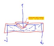
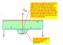
Under such conditions STM is not an appropriate design methodology. Neither is "reinforced concrete" for that matter. The problem is one of "anchorage" that relies on concrete tensile resistance (frustum breakout), similar to conventional anchor bolt design. Designers may not like that this is true. But it is true none the less.

c01.JPG
 
b) have a shallow footing depth.
I would argue that footing depth is largely irrelevant if you're attempting to go down the STM / RC concrete path. That, because those paths require you to anchor your bars within the flexural compression block etc, not within the overall depth of the footing.

On the other hand, if one acknowledges that it's really a problem of anchorage rather than STM / RC, then footing depth does come into play because you mobilize a greater portion of the depth of the foundation.
 

Part and Inventory Search

Sponsor