Kurtanius21
Mechanical
- Nov 21, 2024
- 4
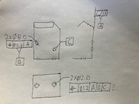
I'm having a lot of trouble determining if the below Position callout is legitimate for or not. I've studied a lot of example positions, but there's not much literature out there for referencing datums not immediately adjacent to the position callout.
Almost all hole position callouts I've seen, the primary datum is perpendicular to the cylindrical tolerance zone. In my case, I've got a primary datum that doesn't contact the hole's cylindrical tolerance zone and is not perpendicular to it either.
I'm torn between understanding that the primary datum should be perpendicular to a hole's axis or datums can just be pictured as how you attach the part to gauges.
The position in question is the red question mark. Theoretically all degrees of freedom are covered for using datums A, B, and C. I'm picturing a flat gauge with two pins sticking out to lock the part in place. But the gauge isn't 'touching' the hole. So is that question mark position callout correct? If it is, can someone explain how it works? What is the meaning behind the datums relationship and position? (Ignore that no basic dimensions locate the holes)

