Continue to Site

Eng-Tips is the largest engineering community on the Internet

Intelligent Work Forums for Engineering Professionals

  • Congratulations pierreick on being selected by the Eng-Tips community for having the most helpful posts in the forums last week. Way to Go!

Substation Engineering - Mechanical loads on anchor portal with uneven span (with insulator chains)

Status
Not open for further replies.

NoFaultRequired

Electrical
Apr 5, 2022
4
Hey there,

I would like to check with you guys how do substation/transmission engineers around the world calculate mechanical loads on anchor portals with uneven spans taking into account the effect of insulator chains.

Altought there are lots of data on how to calculate the loads for even spans with insulator chains I haven't seen any type of analytical development for calculating the forces in uneven spans.

Right now in my company we use an adapted method based on the Overhead Power Lines: Planning, Design, Construction book by Kiessling but when compared with numerical simulation tools the method has shown to be quite conservative.

So I was wodnering if you guys ever saw such method or if softwares are always used for this type of situation.

I know that for transmission line projects softwares like PLSCADD are used, but these are far to expensivce for substation purpouses.

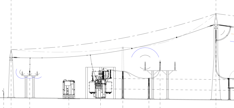
Attached is an example of an uneven span between the 230 kV and 69 kV sectors of a transforming substation.

UneveSpanExample_mftwww.png


Thanks in advance,

Thiago Maia (Electrical Engineer - Brazil)
 
Replies continue below

Recommended for you

That brings back memories, but unfortunately not enough memories.
I had a catenay project about 50 years ago, involving unequal spacing of supports.
A messenger cable supported a trolley duct with supports of varying lengths so that the duct was horizontal with no dips or rises.
It was desirable that each span have the same tension.
With fixed supports, that could be calculated for only one ambient temperature.
Fortunately the mass of the supports was negligible compared to the mass of the messenger and the duct.
Originally, for early catenary systems these calculations were done with a pencil and paper.
At the time of my project, scientific pocket calculators were available.
I hit the books. (This was long before the internet.)
I found a suitable formula and went to work.
Several thousand key strokes later I had a design.

This may be useful:
Britanica said:
Precisely, the curve in the xy-plane of such a chain suspended from equal heights at its ends and dropping at x = 0 to its lowest height y = a is given by the equation y = (a/2)(ex/a + e−x/a). It can also be expressed in terms of the hyperbolic cosine function as y = a cosh(x/a).
It is possible to calculate the drop at any point on the curve.
A support at the proper elevation at any point on the curve will have the same tension and may be placed without changing the curve.
Your challenge, given existing or planned uneven supports is to select a curve that intersects both supports.

Good Luck


--------------------
Ohm's law
Not just a good idea;
It's the LAW!
 
I have used PLS-CADD to model substation bus work. However, there was no incremental cost since we already had a PLS-CADD license and the helicopter had flown over the substations while they were otherwise collecting LiDAR data for the transmission line analysis.

Instead of creating unique tower designs for each bay based on minimizing the tower weights, we typically use standardized substation tower designs. Using standardized components allows for simpler design and installation. Using standardized designs also gives much more flexibility for future changes. PLS-CADD is awesome for analyzing as-builts, but it does not directly include appropriate design margin construction tolerances. For example, it is typical to include enough spare structural capacity in a tangent pole to allow for the pole to be offset from the design location by at nearly a meter, and to allow for the pole installation height to differ from the design height by at least 30 cm.

I used PLS-CADD for upgrading a substation strain bus from porcelain deadend insulators to polymer deadend insulators. The porcelain insulators weigth was very significant compared with the weigh of the short span of conductor, so a ruling span analysis that assumed a parabola was a very poor match for as built conditions. The actual span looked more like a piecewise combination of 3 straight lines such as \___/. PLS-CADD showed we would need to adjust vertical jumper lengths when we swapped the porcelain insulators for polymer insulators.

In the design shown it can be relatively easy for the vertical jumpers to have significant uplift if the installation plan does not correctly account for movement of the 230 kV tubular tower while tensioning the outgoing transmission line, while tensioning the static/shield wires, or for tension changes during extreme cold weather.


Status
Not open for further replies.

Part and Inventory Search

Sponsor