Continue to Site

Eng-Tips is the largest engineering community on the Internet

Intelligent Work Forums for Engineering Professionals

  • Congratulations waross on being selected by the Eng-Tips community for having the most helpful posts in the forums last week. Way to Go!

Support Lug FEA as per ASME Div 2 Part 5.

Status
Not open for further replies.

Sachin Poudel

Mechanical
Jun 26, 2021
13
I did support lug FEA as per ASME Section VIII Div-2, Part 5, Elastic Stress Analysis Method (5.2.2). The model in analysis consists of Support Lug Assembly, Heads, Shell and fillet weld between Support Lug and Shell. The material properties of Shell and Support Lugs are as follows:
Allowable Stress: 16,025 @ 375 F
Yield Stress: 17,925 psi @ 375 F
There is high stress in Weld. How should the stress in weld be interpreted as per Div-2 part 5? What are allowable stress in welds for Elastic Stress Analysis (Div-2, 5.2.2)?

I found that the stress in shell and welds increases as the position of support lug approaches shell-head junction. Can this be due to Secondary stress playing role near the shell-head junction? If so, can we treat the bending stress in weld as secondary stress?
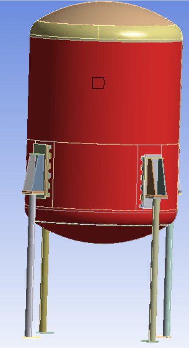
Vessel_with_Support_Lug_n4qv6t.png
Stress_in_Lug_p1wew9.jpg
 
Replies continue below

Recommended for you

Please review the guidance provided in 5.2.1.2. The questions that you are asking are in respect to the categorization of stresses. This requires significant knowledge and judgement. Do you have that knowledge and judgement?

Furthermore, please remember that you won't stop at just the failure mode of Plastic Collapse. You need to carry on to Local Failure, Buckling, Ratcheting, and Fatigue (if applicable).
 
Hi Sachin Poudel,
It seems like your elements are 3D solid continuum elements. Then the calculated Von Mises stresses are PL+Pb+Q+F. Firstly, you should properly select stress classification lines (that is where judgement comes into play, code have some guidance in Annex 5A and WRC429 may help) and linearize stresses at component level and obtain VonMises stresses using these linarized stress components in order to obtain membrane, bending and peak stresses. I do not use Ansys, however it should have a stress linearization tool i guess. After you obtain membrane stress you should classify it either Pm, PL or even as Q in some cases. Similarly, membrane plus bending stresses are either classified as Pl+PB or PL+PB+Q. F is the peak stress calculated with solid elements. Also, please note that if you classify a stress as secondary and limit it to SPS, you shall also calculate the maximum stress range per all load cases required to be checked. (if you classify the stress as secondary you shall demonstrate protection against ratcheting, in other words failure mode is switched and that is an important decision). Also, you should definitely demonstrate protection against local failure and collapse from buckling for that problem.

What i can suggest,

Elastic stress analysis is problematic when the stresses are high as in your problem. Whenever you are not sure, try to verify your design either with analytical calculations or elastic-plastic analysis methods.

Start analysis with shell FE models whenever possible. You can obtain membrane stress at the middle integration point and membrane plus bending stresses at the inner and outer integration points of each element. Therefore, you can eliminate stress linearization process. Annex-5A also describe method to model welds for a shell model.

If you have access to NozzlePro, try to understand how the stresses are classified as primary or secondary, how the stresses at welds are handled for shell models.

 
in my opinon, the weld area should be consider as geometric mutation, so the stress should be consider PL+PB+Q and the limits is 3S
 
Fillet welds are intermittent in the sketch, but must be continuous.

Regards
 
Why does the mesh on the weld not align with the shell or lug mesh?
 
Hi Fraccionadora,
Thank you for your response.

From your reply what I understood is, If we classify the stress as Secondary stress then the failure mode will be switched to Ratcheting. And also the Local failure and buckling have to be checked.

In my case, where I am doing failure from Plastic Collapse, the Stress should be classified as Primary (Membrane and Bending) and Peak Stress only.

Can you confirm this.

I will try Elastic-Plastic analysis as you recommended.
 
Hi r6155,

The Structure itself is not continuously attached to the shell. There is a gap for a half pipe jacket.
 
Hi codyk,

The Shell, Weld and lug are different body so the mesh nodes doesn't coincide.
 
Hi Sachin,

I can confirm with reference to the code as below.
If bending is classified as primary stress,
The stress limit,PL+PB<=SPL, is demonstrated for each load case protection against plastic collapse. [per para 5.2.2.2 Step 5] This check should be done for all required or relevant load cases.

If bending is classified as secondary stress,
Then primary plus secondary equivalent stress range, ΔSn,k shall be obtained considering all required load cases. Then, it should be demonstrated that the stress range of PL+PB+Q stresses are limited to SPS. [protection against ratcheting per para 5.5.6.1]

In your case, as long as you use solid elements and elastic analysis, you shall perform stress linearization [per Annex 5A] to obtain membrane, bending and peak stress components.

 
You modeled the welds, did you model the contact of the weld and the support lugs as well?
What type of contact did you use?
You will have to refined the mesh of the welds, the contact area and align the mesh in the shell and the welds.

Anyway, neglecting the fillet weld from the model and linearizing stress at the junction is generally conservative and eliminate the complexity of meshing the welds.

 
Hi Fraccionadora,

ASME Section VIII Div 2 Part 5 has Stress Classification in Table 5.6 to distinguish between Primary and Secondary stress for Heads, Shells, and Nozzles. How can we distinguish Primary and Secondary stress for Structural components?

Also, For Structural Components which approach do you think will be better among:

1) ASME Div 2 part 5 (Comparing Pl+Pb with SPL and Pl+Pb+Q with SPS).

2) Comparing Tensile, Shear, Bending Stress with
Yield Strength 1 Sy
Tensile Strength 0.6 Sy
Shear Strength 0.4 Sy
Bearing Strength 0.9 Sy
Bending Strength 0.66 Sy
Weld Shear 0.4 Sy
 
Hi IdanPV,

I have made bonded contact of weld with both Shell and the Lug.
 
So, you modeled the fillet welds but you were still tying the shell and lugs to each other using bonded surface to surface, contact set?
I think this is wrong approach.

My suggestion -
don't model the fillet weld and set the contacts to bonded only in a small, thin, area which will represent the "weld".
All other surface between the shell and lugs shall be treated as two separate bodies, you can set some friction between the two bodies.


Hi IdanPV,
There is no direct contact between Shells and Lugs. Both are bonded contact to the welds.
 
Sachin Poudel, Ok sorry. That seems to be the right way.
And still, I would not recommend to model to weld itself, set the contacts in a small, thin, area which will represent the "weld".
 
Sachin_Poudel said:
ASME Section VIII Div 2 Part 5 has Stress Classification in Table 5.6 to distinguish between Primary and Secondary stress for Heads, Shells, and Nozzles. How can we distinguish Primary and Secondary stress for Structural components?

You seem to have ignored my original response - I understand that I am asking the most difficult question of all. Nevertheless, my question gets to the heart of the original question that are looking for an answer to. In short - there is no easy answer - unless you want to demonstrate Protection Against Plastic Collapse using the Elastic-Plastic Analysis Method - then it's an easy answer.

tgs4 said:
Please review the guidance provided in 5.2.1.2. The questions that you are asking are in respect to the categorization of stresses. This requires significant knowledge and judgement. Do you have that knowledge and judgement?
 
Hi TGS4,

I wanted to know about the procedure of distinguishing between Primary and Secondary Stresses in Structural Components.
ASME Section VIII Div 2 Part 5 has Stress Classification in Table 5.6 to distinguish between Primary and Secondary stress for Heads, Shells, and Nozzles. How can we distinguish Primary and Secondary stress for Structural components?

Do you mean you recommend Elastic-Plastic analysis over Elastic analysis as Stress Linearization is not required for Elastic-Plastic Analysis?
 
No guidance is provided in the Code (frankly, nor for free from me) when it comes to stress categorization. As the Code says, you need knowledge and experience.

Yes, I absolutely do recommend the Elastic-Plastic Analysis Method for demonstrating Protection Against Plastic Collapse. 100%
 
Status
Not open for further replies.

Part and Inventory Search

Sponsor