Continue to Site

Eng-Tips is the largest engineering community on the Internet

Intelligent Work Forums for Engineering Professionals

  • Congratulations KootK on being selected by the Eng-Tips community for having the most helpful posts in the forums last week. Way to Go!

Support Types and Their Reaction Forces 1

Status
Not open for further replies.

MatthewMansfield

Civil/Environmental
Aug 11, 2012
47
Hello all

Please dont shoot me down for asking this question as I know it maybe simple for most people.

I am trying to remove doubt from my mind regarding the 3 x types of supports and their reactions.

To me the types of support and their reaction forces are:-

Fixed Support = Vertical Reaction, Horizontal Reaction, Bending Moment Reaction.
Hinged Support = Vertical Reaction, Horizontal Reaction.
Roller Support = Vertical Reaction, Bending Moment Reaction.

To me the above supports can ONLY have those reaction forces - would this be correct?

The reason I ask is because someone told me that a roller support does NOT have a bending moment reaction and i was immediately thrown into confusion.

Can anyone confirm?

Thank you.

 
Replies continue below

Recommended for you

I agree with that someone. Roller can only introduce a load perpandicular to the support surface.
 
Who you argue with, your spouse? If so, you are right :)

image_qdqr8r.png
 
The simplest example of a roller support is an unlocked car tire, it rolls until you hit the break, at that moment (with break applied), it becomes a pin support. Both roller and pin supports do not have moment capacity, as they will rotate about the contact point with the beam they support. However, although no moment capacity at the supports, a simply support beam will fail by moment, why, where is the moment acting on to cause failure? I sincerely hope you know the answer.
 
Whoever you were arguing with is right - for 2D analysis pin is reaction in the x and y, roller is reaction in y, and fixed is moment about z and reaction in x and y. This assumes x is parallel to the support, y is perpendicular, and z is orthogonal to x and y.

Of course this is statics at its most basic level. In reality you have to look at it in 3 dimensions, with reaction forces in all three axes and reaction moments about all three axes. Then you have partial fixity, spring supports, etc.
 
A 2D roller is limited to a single reaction normal to the bearing surface including, but not limited to, a horizontal surface. A 2D roller allows two degrees of freedom, a reaction parallel to the bearing surface and a moment.

The concept should not cause confusion...Fixed, Pinned, Roller = 0, 1 and 2 degrees of freedom respectively.

BA
 
All

Thank you for your responses, I really appreciate it.

Just a follow on question.

The attached drawing (Picture 1) shows a member that support a UDL of 200kN.

The member sits directly on 3 x supports, to me I would describe these supports as roller supports?

If this is correct then they have no horizontal reaction forces which I am happy with.

However since it is a roller support it has no moment reaction but I struggle to visualize this, the flat underside of the member sits directly on a flat horizontal supports - would it be correct to say that the the member rotates about the edge of the supports as shown in picture 2 (forgive my poor sketch, I have highlighted in red circles the rotation points).


Thank you.
 
Let's start with the problem declaration: A member with 200kN/m UDL (Uniform Distributed Load), over 3 support beams. What type of support is typically assumed? The answer can be either one below:

1) All 3 are pin support - this is correct if the member is connected to the support beams through positive fastening.
2) All 3 are roller support - this is acceptable for gravity load only, provides the member is not positively connected to the support beams, and having frictionless medium in between the member and the supports(note this type of support specification violates the rule regarding global stability - the member can move horizontally, but will not affect the analytical results).

Regarding your second question: Theoretically the member will rotate about the centroidal axes. Your sketch depicts the deflect shape of the member with 3 roller support - the supports do not rotate with the member. For the member support on 3 pin supports, at least the outer two supports will rotate with the member, because of the drag force from the connections and shear friction.
 
r13 said:
BAretired in red[/color]]Let's start with the problem declaration: A member with 200kN/m UDL (Uniform Distributed Load), over 3 support beams. What type of support is typically assumed? The answer can be either one below:

I think the OP meant 200kN total load. Makes a big difference to reactions, but it doesn't really affect the answer.

1) All 3 are pin support - this is correct if the member is connected to the support beams through positive fastening.
Three pin supports increase the indeterminacy of the structure by two degrees of freedom and should never be used with a computer program as it will yield incorrect answers. The correct model is one pin and two rollers.
2) All 3 are roller support - this is acceptable for gravity load only, provides the member is not positively connected to the support beams, and having frictionless medium in between the member and the supports(note this type of support specification violates the rule regarding global stability - the member can move horizontally, but will not affect the analytical results).
Three roller supports produce an unstable structure, even in the absence of horizontal applied forces. Should be one pin and 2 rollers.

Regarding your second question: Theoretically the member will rotate about the centroidal axes. Your sketch depicts the deflect shape of the member with 3 roller support - the supports do not rotate with the member. For the member support on 3 pin supports, at least the outer two supports will rotate with the member, because of the drag force from the connections and shear friction.

Pins and rollers are theoretical concepts. They are deemed to be knife edge supports which rotate freely. Real structures do not have knife edge supports. If a support is flat on top, then the beam would tend to bear closer to the edge when it rotates, not precisely at the edge as the bearing area has a finite length.

BA
 
BA,
OP said:
The attached drawing (Picture 1) shows a member that support a UDL of 200kN.
I just wanted to point out the load description (UDL) and the units of the load (kN) do not agree with each other.

Regarding to the 3 rollers system, it is unstable, so theoretically there is no solution, and in reality, no one shall do it. But strictly speaking, in a limit equilibrium situation without any cause for lateral movement, the vertical reaction under each support is identical to that obtained for a stable system.

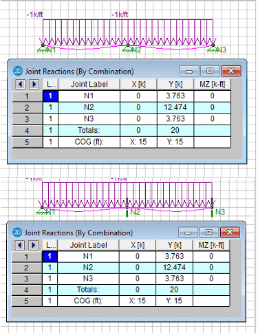
The image below compares results from the 3 pins system, and the system with 1 pin and 2 rollers. No warning was issued from the program.

image_q5agpd.png
 
r13 said:
BA in red[/color]]I just wanted to point out the load description (UDL) and the units of the load (kN) do not agree with each other.

A uniformly distributed load (UDL) can be expressed in kN or kN/m, depending on whether you are referring to W or w (W = w*l).

Regarding to the 3 rollers system, it is unstable, so theoretically there is no solution, and in reality, no one shall do it. But strictly speaking, in a limit equilibrium situation without any cause for lateral movement, the vertical reaction under each support is identical to that obtained for a stable system.

I suppose one could say that the system is in neutral equilibrium, where the slightest lateral force would set the entire beam in motion, but in reality, the structure should be considered unstable. Some software (perhaps not all) would issue a warning.

The image below compares results from the 3 pins system, and the system with 1 pin and 2 rollers. No warning was issued from the program.

I would not expect a warning to be issued for those conditions as they are both stable systems; but you will find different results for shear and bending moment if the supports are placed at the bottom of the beam. With three rollers you should get a warning.


BA
 
Additionally, with respect to the analysis r13 presents above, I'd expect the 3 pin case you present above should have horizontal reactions to maintain equilibrium as the beam cannot shorten under the flexural loading if restrained horizontally at all supports. You get some catenary action and tension in the beams. This is why the beanding/shear/axial/deflections will all be different as stated by BAretired. Not sure why the 3 pin analysis isn't showing an x direction reaction on the N1 & N3 supports?

Everything BAretired has added in his last 2 posts is correct here
 
Agent666 said:
Not sure why the 3 pin analysis isn't showing an x direction reaction on the N1 & N3 supports?

Most likely, the beam was modeled as being rigid or very stiff. No bending = No deflection = no change in the length of the beam = no horizontal forces.

Rod Smith, P.E., The artist formerly known as HotRod10
 
To BA,

To be precise and clear, the conventional description of the loading on the OP's example should be:
- ..the beam has a total load capacity of 200kN, that is uniformly distributed over..., or
- ..the beam supports an UDL of XX kN/m in metric system, or XX plf/klf in the US system.

TO Agent666,

You have raised an important question, though it is not in the OP's query.

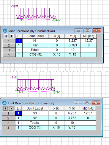
I think in general purpose structural analysis, the program ignores the secondary effect, that produces horizontal reaction at pin support. Evident by another examples below - left end fixed, right end on roller, or pin support. A person familiar with structural programming should be able to point out why, or RISA has committed a mistake.

image_zmhjpq.png


We know in reality, secondary effect shall be included to obtain true reactions afford by the pin support, that is important in design of the connection. Also, in reality, for beam over multiple supports, imo, should be modelled as beam supported by multiple pin supports, unless there is clearly no physical horizontal restrain at the interface, which is rare.

I guess the OP is in the elementary level of structural analysis and design. Wish he/she has knowledgeable mentor around, and study more.
 
I don't know whether all software ignores the secondary effect of a continuous beam, pinned at every support, but I do know that it makes a difference for a simple or continuous truss. The bottom chord of a simple truss is in tension throughout its length, so it must strain accordingly. If both ends are pinned, it can't change length, so pinning both ends of a simple truss is wrong and will lead to incorrect results for member forces.

That has been demonstrated in a thread fairly recently (I forget the name of the thread offhand). Simply extend the rule to a beam, whether simple or continuous. Use at most one pinned support. It doesn't matter which support is pinned. The remainder should be rollers if you want to be sure the results are accurate.

In the case of cable, it's a different story. The cable has an initial sag and the supports must be able to resist the horizontal component of the cable.


BA
 
r13 said:
Also, in reality, for beam over multiple supports, imo, should be modelled as beam supported by multiple pin supports, unless there is clearly no physical horizontal restrain at the interface, which is rare.

That statement is completely wrong, hence very bad advice to give to a young engineer reading this thread. It may be true for some software, I don't know, but it is theoretically incorrect. If the pin supports are placed at the bottom of the beam, where I would expect them to be, all pins are located h/2 below the beam's neutral axis, where h is the height of beam.

In the case of a simple span, the bottom fibres are in tension across the full span. If the ends are pinned, how can that be? A pin at each end means there is no change in length.


BA
 
I'll let the sketch speak itself. [Sketch was withdrawn and revised]


r13,

Your sketch speaks with forked tongue.

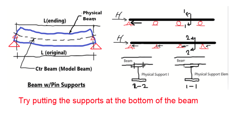
When pin supports are placed at the bottom of the beam, they must resist a horizontal reaction. If there is one pin and the remainder rollers, there can be no horizontal reaction. See simple span at the left in sketch below for support location. The bearing point of a pin or roller is not at the neutral axis of the beam. It is usually at the bottom as you show on Sections 1 and 2.

Try relocating your pin supports h/2 below the neutral axis by using a rigid extension from the neutral axis down to each pin and let us know if you get horizontal reactions.

image_dimnrx.png


BA
 
Unless the beam has a relatively (compared to the load) very large moment of inertia, having more than one pinned connection in the structural model will produce different results for the reactions than if there is only one pinned support. Unless the supports are really very rigid (and it's difficult to imagine how that would ever be accomplished in a real structure), modeling multiple pinned supports will result in model that does not come close to reflecting reality.

Rod Smith, P.E., The artist formerly known as HotRod10
 
I'll let the sketch speak itself.

Unfortunately it's telling lies, that picture is wrong in the sense that if you apply a concentrated horizontal load to the end of the beam at the support location as shown in the bottom picture with 4 pins, all of the H load is resisted by the first pin supoort. The beam doesn't distribute the load to all four pin supports as implied.

You don't need a computer analysis, just some basic understanding of statics (usually 1st year stuff at University) to follow the logic.

modeling multiple pinned supports will result in model that does not come close to reflecting reality.

Exactly.
 
Status
Not open for further replies.

Part and Inventory Search

Sponsor