Continue to Site

Eng-Tips is the largest engineering community on the Internet

Intelligent Work Forums for Engineering Professionals

  • Congratulations KootK on being selected by the Eng-Tips community for having the most helpful posts in the forums last week. Way to Go!

Swept Tool Related to problem...

Status
Not open for further replies.

SORJM

Computer
Apr 5, 2016
30
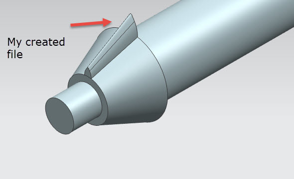
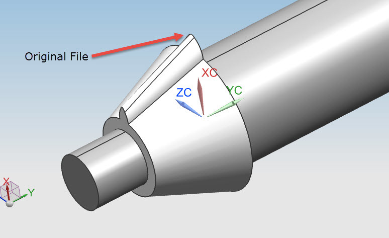
I wanted to create a sweep from an arc and paths, the finished CAD neutral file is attached. And the file I created is also attached.
1_iqmzjq.jpg

2_kqwvd4.jpg


But I am not able to understand why the shape seem to be different. Please suggest some settings in Swept tool or any other method so that I can match it….Thanks a lot.
 
Replies continue below

Recommended for you

In the swept feature there is an option to do the scaling Uniform or Lateral, this is when you use 2 guide strings to control the scaling of the section it moves along. Uniform scales uniformly in the section plane, lateral scales only in the direction between the guide strings , the perpendicular direction is constant.

Try edit the sweep, set the scaling to lateral.

Regards,
Tomas
 
Thanks Toost for the reply I tried it but result is not up to mark......See the image.
9_jw7sjr.jpg

Any suggestion please.
 
But what do we know about the sweep-options that were used in that other system ? ( Catia ?)
If i look at the "original file" , it seems that the "blend" face on the top has a constant size along the sweep. This is either an option in that other system, or it indicates that the blend is a separate operation.

Regards,
Tomas
 
Can you use two guides? Is the pitch parallel to the cone? Use one swept guide curve at the center line of the shaft. Then use another guide line that maybe or maybe not parallel to the cone feature? Sketched on the datum coordinate system. On a bevel gear the root angle is not the same as the pitch angle. I added an image for you. I do not know if this is what you are after. Thanks
 
Not to muddy the waters, but if it were me, first I'd take the "original file" and examine the "blend" face which Toost pointed out (Info -> Object -> Face) and find out if the blend face is a B-SURFACE or not. If a B-SURFACE, I'd try Optimize Face under the Synchronous Modeling tools to see if I could get a blend face out of the B-SURFACE. Chances are it might be a conical blend, which can be dealt with by either an Edge or Face Blend (if you Sweep with a sharp edge).

If that didn't work, then SDETERS is probably on the right track - the guide more than likely needs to be angled. Maybe Sweep it past the planar surfaces and use Trim Body to cut it down to proper size. Nothing against the full Sweep, I just prefer blending with features rather than putting them in my sections (most of the time). Six of one, half dozen of the other.

Tim Flater
NX Designer
NX 9.0.3.4 Win7 Enterprise x64 SP1
Intel Core i7 2.5GHz 16GB RAM
4GB NVIDIA Quadro K3100M
 
Please watch the following Youtube Video to know the specification of the Sweep created in the other software that I want to create in Nx...Any help will be appreciate.....
Link


Seeing the video, it looks like a "NX variational sweep", the sketch has a chord dimension (0.79) which dictates what i mentioned above.- the constant size/ choord. The Variational sweep will can do this.
Note that this option, the constant choord, can be done using the Aesthetic face blend, you can do the sweep w a sharp edge and then apply a blend separately.

The initial question,.... Why do we do this in the first place ? - This model is hardly something to be produced, Are we comparing NX w Creo ?


Regards,
Tomas


Toost I am not comparing the strength of software. I work on different CAD application and teach people the working process of different CAD software. In creo that was not variational sweep as I shown in the video I was general sweep.
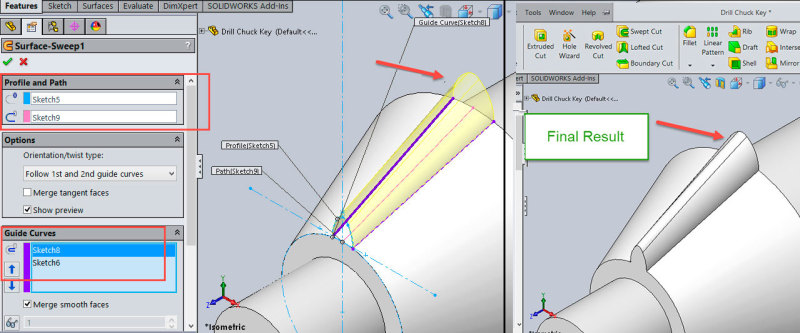
When I created the same thing in solidworks it was more easy and used surface sweep the result was good. See the image below describing the Profile, Path and Guide Curves.....
66--Final_srgqeb.jpg


I am new to NX and wanted to know the correct working way in the software and I got help from you experienced people in the past and wanted the same currently.

Thanks for replying my questions.
 
SORJM, SWorks did not create the same solid as is in your original post, either.

Check again. Even the untrained eye can see it is not the same result.


Proud Member of the Reality-Based Community..

[green]To the Toolmaker, your nice little cartoon drawing of your glass looks cool, but your solid model sucks. Do you want me to fix it, or are you going to take all week to get it back to me so I can get some work done?[/green]
 
The difference between a "Sweep" and a "variational sweep" in NX is that The Sweep feature uses the curves from the sketch, ( It ignores the dimensions/ constraints) the shape of these curves will be interpolated during the sweep. The guides and the options selected dictate the resulting shape. In a Variational sweep, it's the dimensions and constraints in the sketch that rules, all along the sweep.
Thereby the difference on the chord length of the "blend". In the variational sweep , the dimension 0.79 will dictate this all along.

As soon as i remember how to do a Variational Sweep i will upload an example. :)


Regards,
Tomas
 
Thanks Toost that is nice I will be happy to get your assistance... In past your replies helped me a lot. You guidance for the community is quite appreciating.
 
Status
Not open for further replies.

Part and Inventory Search

Sponsor