Continue to Site

Eng-Tips is the largest engineering community on the Internet

Intelligent Work Forums for Engineering Professionals

  • Congratulations KootK on being selected by the Eng-Tips community for having the most helpful posts in the forums last week. Way to Go!

Switchgear Load Increase 1

Status
Not open for further replies.

Esmali

Electrical
Jul 15, 2018
9
Hi guys,

Someone asked me about adding a new load (probably 4MVA to the following switchgear and just looking at the single line and based on the rating I said, it depends on,

[ol 1]
[li] If swg and breakers are in good condition (I don't know if there is any standard way to distinguish swg with a good or bad condition)[/li]

[li] If there is a physical space at the bottom of Swg and also enough (spare) lugs to terminate the new cables in P1 and P2[/li]

[li] If there is enough spare conduit for the new cables in underground ductbank (to connect to P1 and P2)[/li]

[li] Settings of the old relays should be changed to count for the new loads as well (is it that simple?)[/li]
[/ol]


I have not worked with old swithchears and I am sure I am missing things. I would appreciate any comment on this.
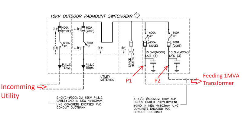
SWG_z5tzxz.png
 
Replies continue below

Recommended for you

No breakers, no relays or relay settings; that's all fused gear. P1 and P2 probably aren't both feeding the same transformer. While a 200E fuse won't melt below 400A (per the curve) it also isn't intended for continuous use above 200A. Assuming the two incoming lines are interlocked alternate sources and a voltage of 12.47kV the gear is good for 4.3MVA, so I doubt that you're going to add 4MVA to the existing without exceeding 4.3MVA.

The gear itself is probably rated 600A, so if larger fuses are possible you may be able to get closer to 12MVA.

What's the utility have to say?
 
To me, this looks like RMU (Ring Main Unit).
The two outgoing feeders are already marked for 1MVA transformers and there is no scope for adding any additional load to the same switchgear.
I guess you need to add a new RMU for the additional loads.
One of the Incoming cables will be looped-in looped-out of the new RMU.
Current carrying capacity of main cables could be an issue. This is to be verified / confirmed for adding loads.

Rompicherla Raghunath
 
What is the incoming circuit - ring, single main, tied main, etc.
What is the existing load. I don't understand how you'd hook a single transformer to 2 different switch and fuse circuits or why you'd want to. So, is it 1 transformer or 2 as the load?

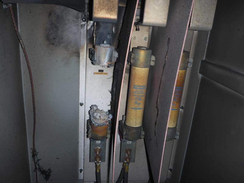
Here's what happens when you try to put a current somewhere in the range of 200A to 400A continually through a 200E fuse.

P1010355_rwea9m.jpg


That is why E fuses are poor stand alone protection devices and should be used with a protection relay.
 

@ davidbeach,

[ul]
[li]You are right, only P2 feeds the 1MVA transformer (P1 is spare for future expansion) utility provides the power only on one of the incoming feeders.[/li]
[/ul]

[ul]
[li]Utility provides the power only on one of the incoming feeders and they can provide 6.5MVA on that feeder (we don't have a limitation there anyway).[/li]
[/ul]

[ul]
[li]So considering there are only fuses (no relays and breakers), the main concerns would be,

[ol 1]
[li]the possibility of the Cable termination in P2[/li]
[li]defining maximum load that can be drawn by the new underground cable connected to P2 without overheating [/li]

[/ol]

[/li]
[/ul]
 

@ RRaghunath,

Having 200E fuse in P2, we can get 1.7*12.47kv*200A=4.3MVA out of it and now we are only feeding 1MVA transformer.
Why we can't connect another 3.3MVA to P2?
 

@ LionelHutz,

[ul]
[li]You are right, only P2 feeds the 1MVA transformer (P1 is spare for future expansion) utility provides the power only on one of the incoming feeders.[/li]
[/ul]

[ul]
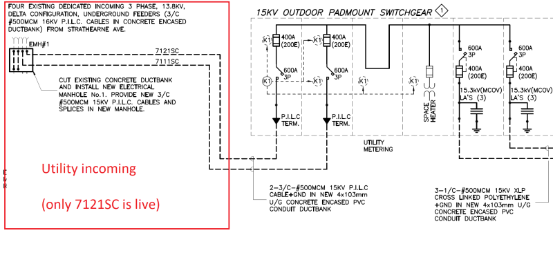
[li]I only have the following single line but the email that I saw from utility says, "We can provide 6.5MVA on a single feed feeding the MVA switchgear ...".[/li]
[/ul]


util_k6iiyt.png
 
So you will be loading up one of the incoming fused switches to 209 Amps on 200 E fuses?
Forget the outgoing load, look at the load on the single incoming circuit and switch gear.
The utility sketch shows 13.8 kV,
You mention 12.47 kV.
That will take you up to 231 Amps on the 200E incoming fuses.
Bill
--------------------
"Why not the best?"
Jimmy Carter
 
You asked about adding 4MVA, not 3.3 MVA. The answers are not the same.

Somehow this feels like it is comparable to my old adage that if the inspector ever has to break out the tape measure to check clearances you don’t have sufficient clearance regardless of what is measured. In this case if you’re shaving the size of the load to be added you don’t have the necessary capacity. What if you convince yourself it really only is 3.3 but turns out to be 3.65? Do you want Lionel’s picture to be applicable to your site?

I’d start by exploring the possibility of something more than 200E.
 
It's rather simple. You can not connect a 4MVA transformer to that gear unless you can either increase the size of the main fuses on the single feeder in use or feed both incoming feeders equally to spread the load between the 2 sets of 200E fuses. If using the latter, you/'d likely want some secondary protection to ensure the load remains split between the feeders so you don't melt down a fuse.

 
A bit of background on this gear,

The city is the owner of this gear and an empty land and they want to see if they can put some modular data centers in it. Data centers can range from 50KVA to even 4MVA and I wanted to advise them on the maximum load that they can put on this gear without buying new equipment. Considering the above discussions, is it fair to say,

[ol 1]
[li]gear rating is limited to 13.8Kv*200A*1.7=4.6MVA and loading 80% of it should be OK (3.7MVA).[/li]
[li]Can the new cable termination be a bottleneck (inside the gear)?[/li]
[li]Is it expensive or even doable to revamp these old gears? Any code that may prevent a change such as increasing 200E fuses?[/li]
[/ol]
 
The incoming switches appear to be 600 Amp rated. Can the 200E fuses be up-sized?
The incoming sections are your first bottle neck.
The utility supply of 6.5 MVA may be based on 80% of a conservative ampacity rating of the 500 MCM feeders.

Another option, if the data center grows past 6.5 MVA:
This may be easy, difficult or impossible depending on the physical layout of the switch-gear and the cooperation available from the manufacturer;
Remove the jumpers between the incoming switches and between the outgoing switches.
Now you will have feeder #7111SC feeding the left-hand outgoing switch (P1).
Up-size the fuses and you have 6.5 MVA capacity.

Install bus bars or cables from the left-most incoming switch through the metering section to the right-most outgoing switch (P2).
Up-size the fuses and you now have a second supply with another 6.5 MVA capacity.
Check with the utility as to the system capacity for the availability of a second 6.5 MVA supply.
You may consider the merits of adding a tie breaker.

Alternatively, leave the switch-gear as it is for 6.5 MVA capacity with the redundancy of a second feeder.


Bill
--------------------
"Why not the best?"
Jimmy Carter
 
waross,

Incoming and outgoing feeders look identical, why do you think the incoming is the bottleneck?

Have you had any experience in revamping used gears like this? Is this something that Switchgear manufacturer can inspect and tell if they can do it or not?

Think big, believe big, act big, and the results will be BIG!
 
The utility's provision of 6.5 MVA is consistent with only one feeder being used at a time.
"We can provide 6.5MVA on a single feed feeding the MVA switchgear"
Yes, on a number of occasions we worked with a factory engineer to modify existing switch-gear to accommodate a customers expansion plans.
Typically there would be a weekend outage for the engineer to measure the needed bus bars.
New bus bars would be fabricated by the factory.
There would be a second weekend outage for our electricians to install the new bus bars and switch gear.
Our boys loved the work. The new bars never quite fit and there was always a few extra hours at premium pay, reworking the new bus bars under the engineer's supervision.


Bill
--------------------
"Why not the best?"
Jimmy Carter
 
"Is this something that Switch-gear manufacturer can inspect and tell if they can do it or not?"
Maybe yes, may be no. We can't tell with the information provided.
Ask the manufacturer what they can do for you.
You seem to have lots of space. It may be an option to install a horizontal chase or enclosure across the rear of the switch-gear to carry the modified bus bars.
The first step, look into upgrading the fuses. That may gain you up to 6.5 MVA total.
A new set of fuses is a really cheap upgrade.

Bill
--------------------
"Why not the best?"
Jimmy Carter
 
OP said:
Is this something that Switchgear manufacturer can inspect and tell if they can do it or not?
Only one incoming feeder is energized. The capacity is 6.5 MVA
There are two outgoing feeders identical to the in-use incoming feeder. 6.5 MVA capacity in versus 6.5 MVA x 2 = 13 MVA cable capacity out.

Bill
--------------------
"Why not the best?"
Jimmy Carter
 
The incoming is the bottleneck because of simple math. 1MVA one one load switch plus 4MVA on the other load switch is 5MVA on the single incoming switch. At 13.8kV, you could have 1MVA on one load switch and 4MVA on the other load switch without changing fuses. But, you can't expect 5MVA from the source through one set of 200E fuses.

4MVA @ 13.8kV is 167A so in theory it would work and be within the fuse rating. But, I personally would be hesitant putting 4MVA of load onto a 200E fuse.
 
Status
Not open for further replies.

Part and Inventory Search

Sponsor