Continue to Site

Eng-Tips is the largest engineering community on the Internet

Intelligent Work Forums for Engineering Professionals

  • Congratulations waross on being selected by the Eng-Tips community for having the most helpful posts in the forums last week. Way to Go!

symmetry in a drawing

Status
Not open for further replies.

idanbrk

Mechanical
Jun 23, 2014
20
hi everyone,

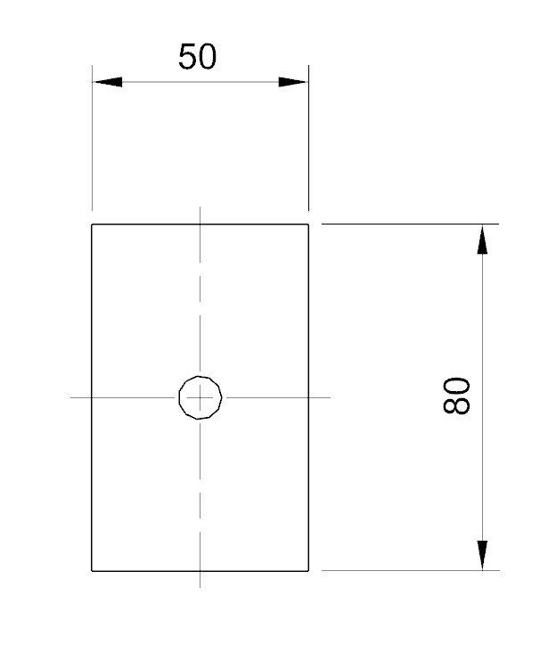
i have a question about symmetry in drawings , what is the correct way to indicate symmetry on a drawing in such a way that i wont have to write the dimensions of features that are in the middle of the symmetric part , its a little hard to explain in writing so i have an example in the attached photo , what i want is not to use the dimensions 25 and 40 that specify the distance to the center of the hole but rather that this dimensions will be implicit from the symmetry of the part.

thanks.
 
 http://files.engineering.com/getfile.aspx?folder=72d074b4-122d-4896-9adc-1ccb7f3889cd&file=plate.png
Replies continue below

Recommended for you

I guess you could imply symmetry by placing full length center-lines, as shown below:

Symmetry_on_a_Drawing_c0t7t6.png


John R. Baker, P.E.
Product 'Evangelist'
Product Engineering Software
Siemens PLM Software Inc.
Digital Factory
Cypress, CA
Siemens PLM:
UG/NX Museum:

To an Engineer, the glass is twice as big as it needs to be.
 
1) Forget implied symmetry - it doesn't really exist no matter how long your center lines or now nicely you overlap the C & L etc.. So I'm afraid the guess above is just that and it's wrong (At least to ASME Y14.5 and and far as I know ISO unless maybe invoking 2768 correctly or something), sorry John. The trouble with trying to imply symmetry is what is the tolerance limit on that symmetry? See ASME Y14.5M-1994 section 2.73.

2) In your case I'd probably have done something like Checker Hater depending on function etc. Here is his illustration imbedded.

download.aspx


Posting guidelines faq731-376 (probably not aimed specifically at you)
What is Engineering anyway: faq1088-1484
 
The fact that the original drawing showed basic dimensions for the 25 and the 40 says to me that you don't necessarily need the hole to be centered. Rather, you need it to be at the prescribed distance from the respective datums, which would be derived from those edges. This would place it in the middle of the part on a perfect part. So perhaps the suggested answer is not quite the same thing?

John-Paul Belanger
Certified Sr. GD&T Professional
Geometric Learning Systems
 
Hence, "I'd probably have done something like Checker Hater depending on function etc."

Also the OP says "what i want is not to use the dimensions 25 and 40 that specify the distance to the center of the hole but rather that this dimensions will be implicit from the symmetry of the part"

Posting guidelines faq731-376 (probably not aimed specifically at you)
What is Engineering anyway: faq1088-1484
 
Gotcha, Kenat. I just wonder why the OP had them as basic dims... my take is that the question about how to dimension something in the center of the part is different from the question about how to tolerance something in the center of a part. (For that, more info would be needed.)

John-Paul Belanger
Certified Sr. GD&T Professional
Geometric Learning Systems
 
Do you need the hole centered in the block, or the block centered about the hole?
 
Status
Not open for further replies.

Part and Inventory Search

Sponsor