Continue to Site

Eng-Tips is the largest engineering community on the Internet

Intelligent Work Forums for Engineering Professionals

  • Congratulations waross on being selected by the Eng-Tips community for having the most helpful posts in the forums last week. Way to Go!

Tension in bolt assembly due to eccentric loading 1

Status
Not open for further replies.

CivilSigma

Structural
Nov 16, 2016
100
Suppose that a ribbed slab runs over a wall (the rib is perpendicular to the wall), and you want to transfer shear force from the web of the slab to the wall below.

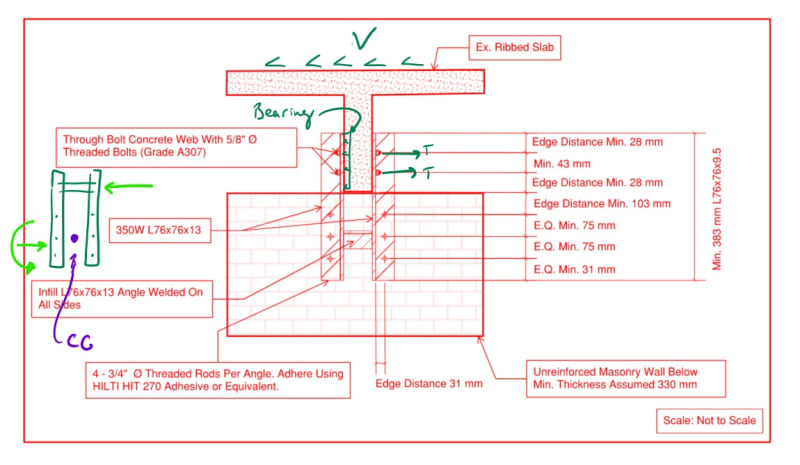
One way to do that is to connect the rib to the wall using a steel angle, bolted to the concrete web on one angle flange, and then bolted to the wall on the other flange as shown in the attached.

From a geometry perspective, and how the shear force is transferred from the concrete web to the wall below, wouldn't you agree that the bolt assembly in the wall is subject to an eccentric moment: M= Ve, where V is the shear force transferred, and e is the edge spacing of the bolt (31 mm) in this case?

This moment will cause tension (withdrawal) of the bolts in half of the assembly, and must be considered in the bolt design (adhesive capacity in this case).

My colleague believes that if we make the steel angles rigid by adding an infill angle, then we can ignore the effects of the eccentric moment and tension force on the bolts.

I disagree with that and believe that the bolt group will experience tension regardless of how rigid the steel assembly is because they are independent in the assembly and don't rely on the stiffness of the angle.
Following the load path: concrete --> bolts in web --> steel angle ---> bolts in masonry wall (here they will experience tension due to geometrical eccentricity) ---> steel angle (receives eccentricity from the bolts).

Any thoughts?


 https://files.engineering.com/getfile.aspx?folder=ba331cdc-24a5-42ab-b893-622ad05d992a&file=Capture.PNG
Replies continue below

Recommended for you

I'm assuming your load is parallel to the wall below and perpendicular to the axis of the rib.

For stability, the angles have to be fixed to either the slab or the wall. I think the connection to the wall will be stiffer, so I'd look at it as if the wall connection is fixed. So all of the bolts in the masonry wall will be in shear with resultants going off at different angles. At the slab, one angle will be bearing on the concrete web while the other will be pulled along by the through bolt in tension. I'd just assume equal tension between the two.
InkedCapture_LI_jbxe3c.jpg
 
would the dominate loadpath for bending be a couple between the two angles ? A secondary loadpath would be bending in the angles.

the angles transfer the shear (one loaded by bearing, one loaded by the bolts (in tension) ... possibly the bearing loadpath is primary and the bolt tension secondary.
Then the angles would be in bending as the shear moves from the parting plane to being sheared on the fasteners into the supporting masonry wall.

Draw FBDs of each element ...

another day in paradise, or is paradise one day closer ?
 
Another thing - that rib doesn't look all that thick. I'm guessing it's not to scale? Those aren't usually designed for out of plane bending, so be sure you don't have a weak link there.
 
Based on your description and drawing, it sounds like what you're saying is that, referencing your drawing, the shear load being transferred is normal to the page (IE load is parallel with the ribs in the slab)

If that's true, then I agree with you, that the tension absorbed by the bolts is independent of the stiffness of the angle. The only bolts that would actually see any tension would be the two closest to the load.

If the load is, in fact, east or west on the page (perpendicular to the slab web) than tension can only be applied by rotation of the flange (forcing it out of plane with the wall, which in turn can only happen if the flange against the beam web is free to rotate. The flange to which that infill angle is welded, below the bottom of the edge of the beam web, isn't doing much for you. In my opinion the actual tension developed into those bolts is going to be very, very minimal. There just isn't much unsupported length of that angle to provide displacement (via rotation away from the wall, out of the page plane) and if there's no rotation the bolts aren't attracting any tension.
 
The load is into the page, being transferred from the concrete to the wall below.
So, the load is in-out of the page with respect to the beam, then transferred east-west to the wall below.


I want to make a clarification based on the replies (maybe I have a fundamental misunderstanding):


How can the bolts be engaged in pull-out while attached to the masonry wall?

After reading your comments, I am understanding that it is only possible when the angle it self pushes outwards on the bolts. Now, if the angle is "rigid", that won't happen. But if we have a flexible thin angle, it might occur.

Is that correct? ( I agree with this, but still believe a group of bolts can experience pull-out due to eccentric loading, which is independent of whether the angle is rigid or not).


@Pharmeng
You're saying that the wall connection to the angle is rigid, therefore there won't be pullout on the bolts in the wall. Why? What happens to the effect of eccentric moment on the group of bolts in the wall?


Also, I don't understand how there will be tension/pullout for the bolts in the concrete web. To me, they will be in bearing against the concrete of the web as they are placed perpendicular to the force.

@SwinnyGG

In your second paragraph: Yes, I agree. The bolts would be loaded in tension in the wall due to the eccentric moment. When you say the two closest to the load, do you mean the top two bolts in the wall ?

In your third paragraph: I also agree, if the load is originally east-west, basically being transferred from the wall into the beam, then the bolts in the wall are in pure shear, the bolts in the beam are in pure tension and will experience additional tension force from the eccentricity of the bolt group in the steel assembly.
 
CivilSigma said:
do you mean the top two bolts in the wall

Yes. If the wall is 'static' and the load is trying to pull the beam out of the page, the only bolts that see any added tension, above their initial installed preload, are the top two. No matter what you do to that angle, it will never be infinitely stiff; tension can't migrate down past those first two bolts unless they fail.
 
Alright. I thought the load was across the page. I don't see how it can be into the page. Is that diaphragm shear that you're trying to dump into a unreinforced masonry wall perpendicular to the wall's axis? Have you checked the wall? Any load that doesn't rip that apart is probably so low that the angle and bolts won't care.

For sake of argument we'll assume that the wall somehow can resist this out of plane load.
Screenshot_2021-12-07_170326_gn8ssc.png
 
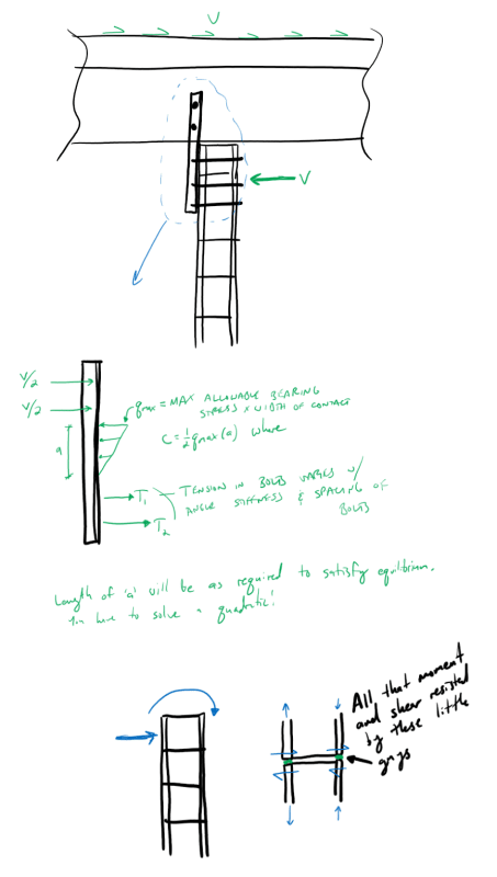
Right...the rigid angle idea...doesn't work. Statics is statics. Yes, the distribution is dependent upon the stiffness, but you'll never reach ideal rigidity and you'll always have to account for eccentricity.
 
If I'm understanding the configuration and loading correctly, the anchors in the wall will experience direct tension as the angles try to rotate, either pivoting over the top edge of the wall, or about the bottom end of the angle, depending on the direction of the force.

This will be the initial forces. However, once some movement occurs (i.e. the anchors start to pull out of the wall, further movement will be resisted by a force couple producing shear on the 2 through bolts in the stem.

The moment due to the eccentricity between the stem connections and the anchors in the wall produces torsion on the angles, which will be resisted mostly by the infill angle.

Rod Smith, P.E., The artist formerly known as HotRod10
 
Is that diaphragm shear that you're trying to dump into a unreinforced masonry wall perpendicular to the wall's axis? Have you checked the wall? Any load that doesn't rip that apart is probably so low that the angle and bolts won't care.

Now that phamENG pointed out that it's an unreinforced wall, I agree that the limiting capacity will most likely at the masonry, with or without the infill angle.

The eccentricity moment causing torsion/prying on the anchors is a minor portion of the tension load on the anchors, and an inconsequential tension load on the through bolts.

The lateral force/shear on the wall is going to be the problem. If you can figure out how to make the wall resist that force, I would suggest you move or extend the angles up farther on the stem, so that you can get more separation between the two through bolts, thereby increasing the moment resistance of the bolts in shear, and eliminate the anchors in the wall.

Rod Smith, P.E., The artist formerly known as HotRod10
 
Status
Not open for further replies.

Part and Inventory Search

Sponsor