Continue to Site

Eng-Tips is the largest engineering community on the Internet

Intelligent Work Forums for Engineering Professionals

  • Congratulations KootK on being selected by the Eng-Tips community for having the most helpful posts in the forums last week. Way to Go!

Thermal expansion and components placed opposite each other (Nozzle loads)

Status
Not open for further replies.

Marcin Wysocki

Computer
Oct 11, 2023
3
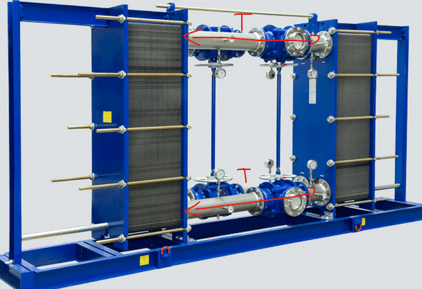
How to analyze nozzle loads for two plate heat exchangers arranged as in the image below? How to interpret large forces along the pipeline axis resulting from thermals? such systems are commonly used and are not damaged.
pastedimage1696413939735v1_nuracj.png


I assume that obtaining nozzle stiffness values from the manufacturer will not be an easy task, and in some cases, it may even be impossible.

...but I assume that the axial stiffness (especially of the lower cooler connections) is very high.The axial thermal forces calculated by Autopipe on these connections will be enormous, and it may be impossible to meet for e.g. the API standard.

As I mentioned above, systems of this type operate in many installations wihout damage or failure. I am wondering how to prepare a nozzles load analysis in a way that will allow to meet the standard e.g. API 662.

Regards
Marcin Wysocki
 
Replies continue below

Recommended for you

You will have to allow expansion the equipment items to expand unhindered. The attached piping should be flexible enough to not resist such movement.

Short lengths really do not expand very much and the slight movements of the frames will hardly be visible at all. It's basically a numerical problem that goes away when 1mm of movement takes place. Just don't make the frame "too strong".

If you need to place an anchor for numeric stability, place it at the center of the expanding equipment and allow the equipment nozzles to move outward in two directions.

If movements are high enough to visibly bend the frames, anchor one frame and put the other on a sliding base plate with slotted bolt holes, or some kind of slide track arrangement.

--Einstein gave the same test to students every year. When asked why he would do something like that, "Because the answers had changed."
 
This is where real life situations meet unrealistic analysis programs.

As Mr 44 says, so long as the temperature rise is relatively low ( say 30-40C) the actual amount of movement is very small and will be taken up in the gaskets and some minor deflection of the nozzles. The analysis program though will spit out huge forces based on no deflection or movement at all.

So either model it with a sliding support from the HX to the frame and then see how much it moves or fit some sort of bellows or flexible pipe.

Or don't bother as the vendors will either give you some ridiculously low value of acceptable force or not provide one at all.

Remember - More details = better answers
Also: If you get a response it's polite to respond to it.
 
Agreed this is a frustrating situation. Even on projects where the equipment spec says the vendor needs to provide non-zero allowable loads, they just say they can't or will do so for $$$ and a schedule impact.

The best approach is like the others have suggested which is to recognize that equipment will deflect/deform slightly at temperature. Aim to keep your external piping loads in a reasonable range based off the size/connection and it should be okay.
 
Are you building the entire skid shown and are assigned to analyze the loads on the heat exchanger nozzles due to the piping shown? Or are you purchasing the entire skid shown and just connecting up to it with piping at the connecton points shown?

 
As mentioned, the length of pipe between the two exchangers is pretty short. Also, the only fixed anchorage between them are the angle brackets at the bottom and the threaded tie rod at the top, which do not appear to be extremely rigid.
 
If that spool is 1500mm and the temp increase is 40C it expands by 0.7mm as a free expansion.

That's a ridiculously small expansion.

Just don't worry about it.

As you say many systems work no problem.

Remember - More details = better answers
Also: If you get a response it's polite to respond to it.
 
Thank you all for the quick responses.
You have confirmed what I was thinking about this topic.

@Snickster - Yes, we need to design an entire skid similar to the one shown in the picture.

Once again, thanks to all of you.
 
LI said:
If that spool is 1500mm and the temp increase is 40C it expands by 0.7mm as a free expansion.

That's a ridiculously small expansion.

Exactly that. There's a cut-off below which you shouldn't be bothered with analysis outcomes, or real-life measurement for alignment either.

All of our plants are modularly built, so each item (frames, vessels/equipment, and piping) is prefabbed.
We have that any deviation below 3 mm (roughly 1/8 in.) isn't considered, since (i) the measuring device may not be accurate, and (ii) the interface to each other (e.g. frame to equipment, or piping to the bracket to the frame) may also not be aligned within 3 mm accuracy). hence we have a similar rule of thumb for expansion, however, I'd say consider 1.5 mm and above to be relevant (i.e. the rule of thumb).

Huub
- You never get what you expect, you only get what you inspect.
 
Thank you all for your responses. I now have a clear understanding, but I'm unsure how to present or articulate it in the client report. Any guidance would be appreciated. [ponder]
 
Het a copy of book on piping design and (preferably) pipe stress analysis. For example Peng, Becht or Spielvogel. Read manuals of for example AutoPIPE or Caesar’s II (if you have a copy) on things like pipe support lift off (hot sustained). Such references have a good explanation on why certain allowances are acceptable to the codes.
They will also, as a bonus, learn you a thing or 2 (more) on piping design.

Huub
- You never get what you expect, you only get what you inspect.
 
If you've already done the stress analysis, say you're assuming the HX structure supporting has a stiffness of XYZ. Note if the frame stiffness is too high, additional forces due to thermal expansion of the piping will be experienced.

If you're designing this skid/HX, tell whoever doing the structural design the requirements.
 
Status
Not open for further replies.

Part and Inventory Search

Sponsor