Continue to Site

Eng-Tips is the largest engineering community on the Internet

Intelligent Work Forums for Engineering Professionals

  • Congratulations waross on being selected by the Eng-Tips community for having the most helpful posts in the forums last week. Way to Go!

Thick walled cylinder under normal compression against flat surface 1

Status
Not open for further replies.

n8th8n

Mechanical
May 13, 2015
3
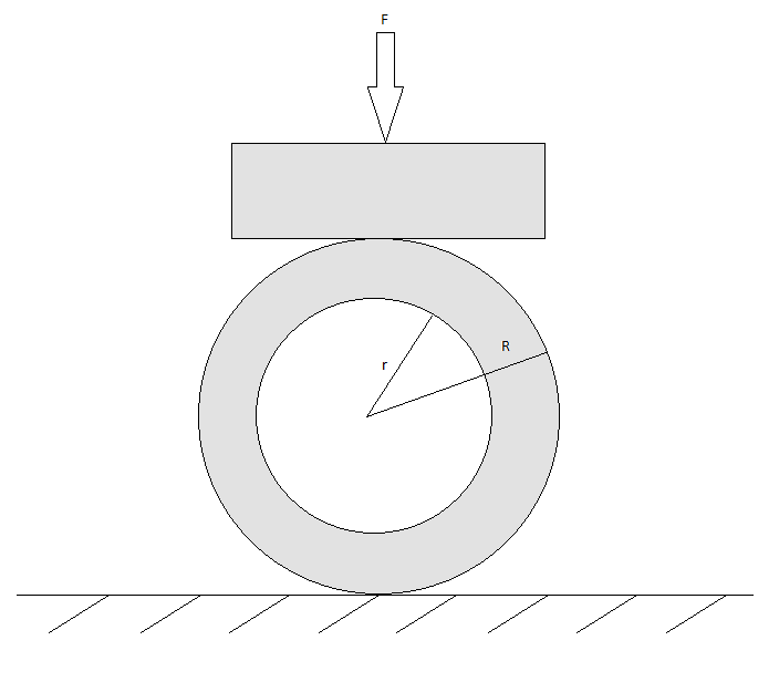
I'm trying to analyse stresse in a metalic tube, which is held in place by a flat bottom lock screw (See figure). In the study, R will remain constant, L is a constant length, and r will vary. We will assume no friction, smooth surface, isotropic linearly elastic material with σ[sub]y[/sub] representing the yield stress. The study will investigate the required compressive force (F) at σ[sub]y[/sub].
Tube_Compress_qka5z1.png


I've tried to find a general solution to this problem, but so far it has evaded me. I've also been trying to perform and FEA through ANSYS, however my experience with ANSYS is limited, and I find this non-linear contact problem is not trivial, and I can't seem to get the solution to converge.

Could anyone assist me in tackling this problem either with ANSYS or arithmetically?
 
Replies continue below

Recommended for you

If the support on the bottom and the load on the top both extend along the full length of the tube, or can reasonably be treated as such, refer to Roark's Formulas For Stress and Strain. Specifically, the load cases with circular rings with two equal and opposing loads. There are adjustments that can be made for a "wide" beam section in those cases.

If the load on the top is essentially a point load or small round load, you have localize bending that might be similar to that found in pressure vessels with loading applied to shell nozzles. Refer to various pressure vessel handbooks or WRC 107 and later versions for approaches to that.
 
Neither r (ID) nor R (OD) will remain constant in the real world.

The cylinder will compress into a horizontally-flattened "double-8" with the maximum defoliation at top and bottom. depending on which fails first (deflects the most) Since every machined part is slightly different in small ways from its predecessor and its follower in the assembly process, every "real world" cylinder will fail differently.
 
I don't see this problem treated as a contact problem, unless you want to analyze the local stress under the load, but then you go into Hertz's contact stress analysis. I would simply treat, in the FEM model, the top load as a line load and the bottom support as a line support (and of course you need also to constrain the rotation there).
The analytical solution is given by Roark, as suggested by JStephen. With r becoming small with respect to R you'll need a correction for thick curved beams that's also provided by Roark.

prex
[URL unfurl="true"]http://www.xcalcs.com[/url] : Online engineering calculations
[URL unfurl="true"]http://www.megamag.it[/url] : Magnetic brakes and launchers for fun rides
[URL unfurl="true"]http://www.levitans.com[/url] : Air bearing pads
 
How is the screw that's holding this in place oriented? I'd be worried about the fact that your load and resistance points won't be perfectly aligned, so your cylinder will try to roll. That instability could be a significant factor depending on how you've restrained it.
 
is this a real work problem ?

I think you can do contact between areas (a portion of the plate, a piece of the outside surface of the tube).

"R constant" will be work ... as you push down with the plate it'll get closer than 2R to the ground (unless that's not what you meant). The contact area will flatten (initially it is an infinitely small line area) and then the tube will bow out and become elliptical.

another day in paradise, or is paradise one day closer ?
 
It should be noted that this is a real world problem that I've simplified for analysis simulations. There's no need to concern myself with instability effects or buckling. I've also been thinking that contact stresses are not important either, since (the real problem is) I am analyzing the effects of introducing a bore into an existing solid rod. Since the existing rod has already been analysed for contact stresses, I should assume they can be neglected in the problem model.

I found the analytical solution in Roark's for a thin walled pipe with a meridian line load, and I'm trying to find the thick walled correction.
 
Status
Not open for further replies.

Part and Inventory Search

Sponsor