Continue to Site

Eng-Tips is the largest engineering community on the Internet

Intelligent Work Forums for Engineering Professionals

  • Congratulations waross on being selected by the Eng-Tips community for having the most helpful posts in the forums last week. Way to Go!

Calculate Normal Force

Calvin Murphy

Aerospace
Nov 22, 2024
16
I am hoping to settle a debate between two engineers.

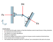
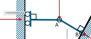
I have created a simple diagram of the part of the structure we are investigating.

It can be solved in 5 minutes or less by anyone familiar with static equilibrium problems.

The goal is simple enough: find Fn.

Yet, the discussion over whose solution was correct is still unresolved. I build a rig to physically measure it, but the disagreement persisted. Then I reached out to 5 university professors to see if they would help, but I have not heard a response. So here I am. Please help.

1738354974883.png
 
Replies continue below

Recommended for you

How about a response from the OP ? What was the nature of the discussion at your end ? Were people arguing over the significance over the symbol of the LH support ?
 
Jesus, people, talk about overcomplicating a basic situation
This is simply solvable by hand or computer in a variety of ways and the diagram given is obviously just a basic representation

Why are we arguing about whether the roller has one wheel or two???
one wheel means pinned
two means no directional restraint.

But having wheel of one and two is funny.

Anyway, by hand calculation, you can resolve it.
Point A provide only Rx.A
Point B provide both Rx.B and Ry.B

Solving for vertical force.
Thus, We know Ry.B is 5N because no vertical reaction at Ry.A

Solving for horizontal force.

Since the angle is 30° so we know the axial of the diagonal member is 5 / sin30 = 10N
Thus, the horizontal reaction Ry.B will be 8.6N
The Ry.A will be 8.6N as well, ignore the directional sign.

Thats why people says it is basic problem because we can get the internal force of this system
And we have someone solve this as shown
None additional requirements or caveats are necessary calculate the static equilibrium answer. The fact that it is stated that the system is in static equilibrium is enough. Of course we should all recognise that this static state is inherently unstable and hence this is a academic exercise not a real world exercise.

As I said earlier if you need extra confirmation then your favourite frame analysis software should give you an answer. Here is my result for what should be a simple statics problem. I've provided two diagram simply to show that geometric length is not relevant.

View attachment 4304


But here is the catch, I don't know how to start develop the bending moment diagram.
That's why people says it is unstable. You are not able to generate deflection diagram as well.
You can only generate shear diagram.

Edit:
In real life this is a very unstable structure that's why everyone here is applying actual and practical thinking in solving this equation. Thus the conclusion of unstable because we could not generate the correct bending moment diagram.
Unless we all see this is solely as academic purposes where unstable is acknowledged but unchallenged for academic purposes.
Otherwise this will not work in real life.
 
The picture I can see has a T shaped horizontal strut with TWO wheels between the vertical and the wall.

Hence it can react moments

1738634758392.png

What picture are you lot looking at?
 
Greg, I'm assuming you're not particularly familiar with the symbols, but the number of wheels isn't generally indicative of two reactions. The question specifies one reaction Fx, there is no reason to believe it's multiple reactions. If the intent of the question was that there are two supports at that end, I would think it would be mentioned. The only purpose that vertical appears to be serving is to show the strut is perpendicular to the wall.

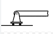
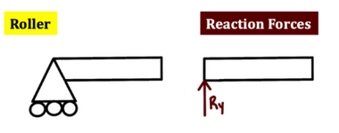
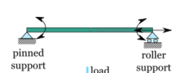
Representing a single reaction with multiple wheels very common, see below examples of a roller being drawn this way. It's not the only way, but it's common enough that it's the main notation I saw used throughout my education and have been using my whole working life.
1738638528289.png

1738638545949.png

1738638590398.png
1738638672572.png
 
I wonder if the academic problem is saying that the small amount of compressive strain in AB is going to cause the LH to separate for the vertical face, and "flop" over ?

As drawn AB is sitting happily normal to the RH face (presumably held by some supporting brace) and the LH strut can swing into place (and support AB) but the compression in AB will translate A away from the wall and the "house of cards" will tumble down.
 
Ah, I'm too used to playing with cars. So effectively there a pin joint between the horizontal and vertical of the LH strut. Okeydoke, that kills most of my discussion.
 
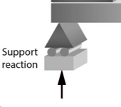
It’s drawn in an unusual, rigid T-shape, which makes it easy to see why Greg interpreted the two wheels as separate rollers. Typically, rollers, despite being depicted with two wheels, include a small triangle seesaw, or pin to indicate that no moment can develop.

In any case, people here are interpreting it differently, which is why theres a debate over its stability.
 

Part and Inventory Search

Sponsor