Continue to Site

Eng-Tips is the largest engineering community on the Internet

Intelligent Work Forums for Engineering Professionals

  • Congratulations IDS on being selected by the Eng-Tips community for having the most helpful posts in the forums last week. Way to Go!

Threaded hole with cutout on the outer surface of a rotor

Status
Not open for further replies.

Mr_Curious

Mechanical
Jul 14, 2020
40
I want to connect the walls of a groove in the rotor with screws so that the size of the groove does not change during rotation. (The groove was machined by mistake). I want to make threaded holes in the groove and screw screws into them. The threaded holes are obtained with a cutout. Have you come across in a books the calculation of a threaded connection with a cutout in the hole like mine? I am interested in how the strength calculation of these connections is carried out.
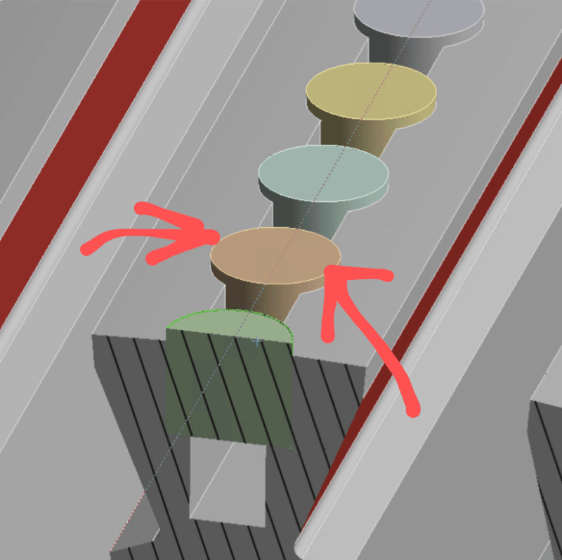
Screenshot_20240923-140907_2_r2alc4.png
 
Replies continue below

Recommended for you

It's not clear what problem that you are trying to solve, or why you think a complicated and difficult to perform repair would be the best solution.

If you can provide some quantifiable information you might get some good suggestions.
 
Hi Mr Curious

I think I understand what you are trying to do, however I don’t think it will work based on the assumption that the threaded hole is machined over the groove and is tapped into both side walls? So from the info you have posted the screw thread runs parallel to the groove walls so any force from the screw and internal thread are acting parallel to the grooved walls and therefore will not pull the walls together. What causes the groove dimensions to change is it purely the rotation of the rotor or is heat involved as well.

“Do not worry about your problems with mathematics, I assure you mine are far greater.” Albert Einstein
 
The standard bolt thread profile will create a wedging action that will open your groove. There is a company, Lock-N-Stitch that makes pins and special taps that have a thread from that does not spread the groove.
 
On the assumption that the screws will be preloaded, approximately 2/3 of the threads will be loaded. The preload will generate thread radial loading, pushing the groove open. The walls of the groove are tapering, the minimum wall thickness being at the base of the groove. You’ll see build stress at this location.
 
It has only been a couple of days, but OP ain't been back since Sept 23, the day of his original post.

I do not understand the axis of rotation ( among other things). And as a result, also not the tendency for "the size of the groove" to "change during rotation."
//Maybe// if the groove was machined radially on a local Outside diameter the groove would tend to pinch shut?

Until material and geometry and rpm and temperature and operating environment ( erosion, corrosion) etc are specified, as well as the maximum allowable deflection, my list of groove stabilizing options to consider includes a large snap ring, commercial o-rings, plastic wood, poured lead or bismuth alloys , lab metal or epoxy, plastic steel, plastic titanium, a series of tack welded spacers, 4 to 20 stop screws in holes tapped thru one ring axially, milling a series of radial openings and a Tee slot low in the accidental groove so several close fitting tee spacers could be installed to prevent pinching.
.
 
Status
Not open for further replies.

Part and Inventory Search

Sponsor