Continue to Site

Eng-Tips is the largest engineering community on the Internet

Intelligent Work Forums for Engineering Professionals

  • Congratulations waross on being selected by the Eng-Tips community for having the most helpful posts in the forums last week. Way to Go!

Three holes on same plane

Status
Not open for further replies.

Sa-Ro

Industrial
Jul 15, 2019
273
IN
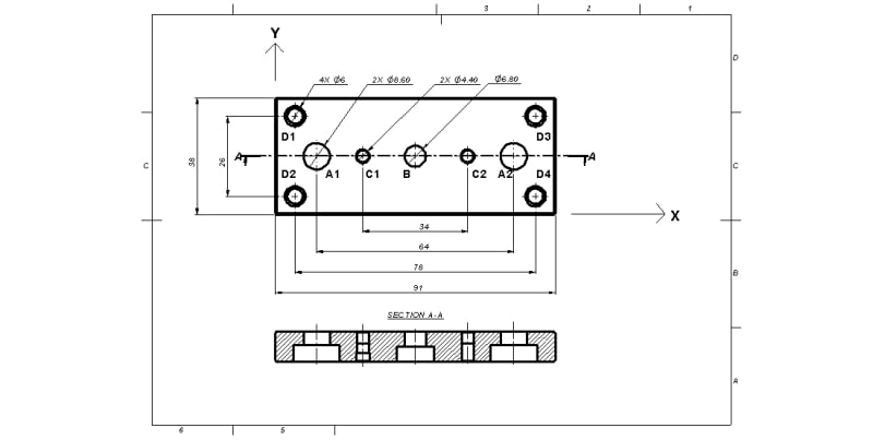
Dear All

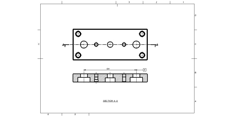
070135_tgnmnd.jpg


Our requirement:

1) Hole A1 and A2 shall be on same plane within variation of dia 0.05.

2) Hole A1 and A2 shall be symmetrical to hole B within variation of 0.05 along X axis.

3) Hole A1 and A2 shall be coincide with a plane passing thru hole B center axis within variation of 0.05 along Y axis.

4) Outer size 91 and 38 shall be aligned as shown in drawing.

5) Hole D1, D2, D3 and D4 shall be symmetrical to hole B within variation of dia 0.05

6) Hole C1 and C2 shall be on same plane within variation of dia 0.05.

7) Hole C1 and C2 shall be symmetrical to hole B within variation of 0.05 along X axis.

8) Hole C1 and C2 shall be coincide with a plane passing thru hole B center axis within variation of 0.05 along Y axis.

Kindly suggest us, how to define our requirement as per ASME Y14.5:2018 GD&T standard.

Thank you.
 
Replies continue below

Recommended for you

I like Sudoku better. Use position tolerances and show your work.
 
Interesting set of requirements.
Is it driven by the function of the part, or did someone just felt like it "shall" be this way? If function is important, describing it might help you get better answers on how to do the tolerancing.
 
Hi

Thanks for your response.

Function of the component:

First: Hole A1 and A2 are attached to a parallel rod thru counter bore - Only for guide.

Second: Hole B is attached to middle rod (between above said two parallel rod) thru counter bore - Reciprocating operation

Third: Hole C1 and C2 are attached to any flat component - From opposite direction to First and Second step - Customer fitment

Fourth: Hole D1, D2, D3 and D4 are attached to any flat component - From opposite direction to First and Second step - Customer fitment

Either Third or Fourth is used at a time. Not simultaneously used.

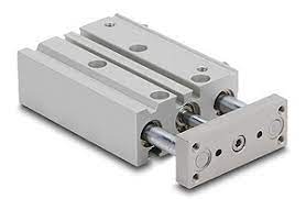
Refer the below image

download_nahdcl.jpg


Thank you.
 
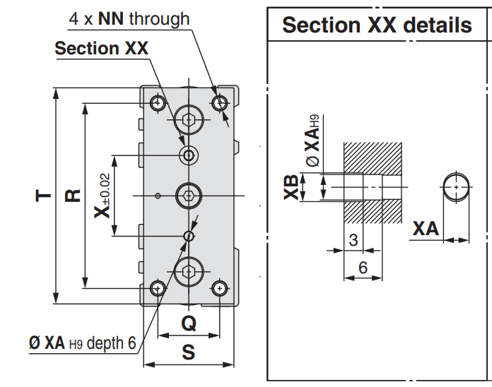
Is this an SMC pneumatic cylinder? Then check the catalog. I know, they won't include manufacturing dimensions. Why would they. But the locating pin holes (and slot-hole) are only ±0,02 so no big deal. The rest is up to you. You want a precision guided cylinder? Then position the holes with Ø0,01 or less.
I'd make the center hole Datum A, then the middle planes as Datum B & C then the rest is gg easy

smc_quot0q.png
 
Sa-Ro, I'm not sure what you mean by "Reciprocating operation" in the second step.

Am I correct assuming that the middle rod and the counterbore of hole B have the closest fit, and the plate is located by it and oriented by it in two directions, and the 2 holes A1 and A2 are used to lock the rotation around the middle rod?
 
It's two outside linear bearings with a pneumatic cylinder in the middle to push and pull - basically, 3 fixed fasteners.
 
Hi

@Wuzhee
I took that image from internet. So not aware of SMC cylinder.

@Burubduk
Yes you are right.

Reciprocating operation means, middle rod will move front and back due to pneumatic pressure. Other two rods are used to arrest the rotation.

As long as the plate not rotating much around middle rod, the product quality is good.

Thank you.
 
Make the counterbore for the middle rod (B) the primary datum feature, and specify position tolerance with reference to it for the two counterbores of A1 and A2 as a pattern. Make this pattern your secondary datum feature, and position the rest of the holes with reference to the primary and secondary datum features.
 
Sa-Ro,

Consider that your part is being machined. The machinist will easily achieve [±]0.2mm, and should be able to do [±]0.1mm. Will a [⌀]0.2mm positional tolerance solve all your problems?

If this were a casting or a weldment, I would specify several holes as datums to accomplish your requirement, with maximum manufacturing allowance.

--
JHG
 
Hi

@Burunduk

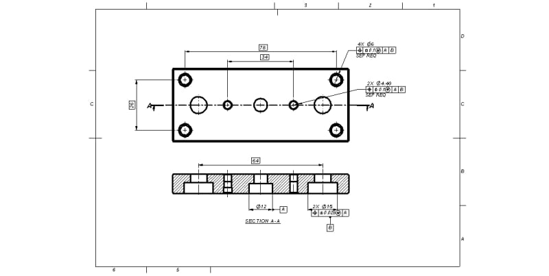
Refer below image. Is this what you are suggesting?

070135-2_qeu8dc.jpg


In this case, we are first locating middle hole.

But we need to first locate two side holes. Because those two rods are already guided within two parallel holes.

Any shift in two hole position will lead to misalignment.

Refer below image. Is it right with our requirement?

070135-1_od6f9o.jpg


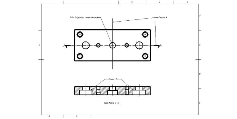
One more doubt. Shall I define location dimension as a datume. Assuming the resulting datum is a plane between two holes.

Refer below image.

070135_t2gmt3.jpg


@Drawoh
We are not concerning about tolerance.

We are focusing on the method how we can rightly transfer our design requirement into drawing.

Thank you.
 
Sa-Ro,

Regarding the choice between the middle counterbore (Ø12) or the two Ø15 side counterbores as the primary datum feature,
It depends on this:
Once the two Ø15 counterbores are engaged with the pair of parallel rods, is the location of the component fixed, or is it still loose and gets constrained only after the middle rod is engaged with the Ø12 rod in the middle? If the latter, then the Ø12 counterbore should be the primary datum feature for position tolerances on the other counterbores and holes, because it is the one which effectively constrains the most degrees of freedom (two translations and two rotations), in spite of being engaged in assembly second.

Absolutely do NOT attach the datum feature symbol to the dimension between holes. It is not a feature of size and such use of the symbol is meaningless.
 
I would go with Ø15 holes, the pattern, as primary. If Ø12 (one hole) is used primary, I think the DRF is not very stable as the hole is very shallow. (Ø15 holes are equally shallow, but at least there are two of them which drastically improves the stability)
On the same token, I would use the bottom plannar surface, maybe as secondary, to improve the stability of the tolerance zones. (some of you will think that's not a value added datum in the DRF....maybe it is for measurement....maybe not)
 
greenimi,
I agree that referencing one of the large flat faces as a datum feature could benefit inspection stability, but I would say it is only advantageous when used as the primary datum feature to constrain 2 rotational degrees of freedom (and one translational degree of freedom which is less meaningful in this case). In such case, I would control the secondary datum feature - which should be function-based, for a tight perpendicularity tolerance relative to the primary planar datum feature, to minimize the difference between how the part is constrained for measurement and the way it is constrained in its functional application.

Note that if the pattern of two Ø15 c'bores is used as the primary datum feature (or as the secondary after the planar face), referencing the middle Ø12 c'bore as secondary (or tertiary) is unnecessary, as it becomes redundant after the two Ø15 c'bores (or the planar face and the two Ø15 c'bores) already constrained the 5 meaningful degrees of freedom (or all 6 degrees of freedom). So this approach essentially totally eliminates the Ø12 c'bore from the datum feature selection scheme. The question is - is this the right thing in terms of function?
 
Using any holes of the exact part in the application as shown in the photograph as primary is a mistake.
 
Hi

Thanks for all your feedbacks.

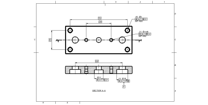
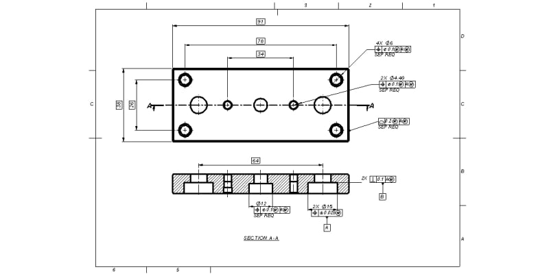
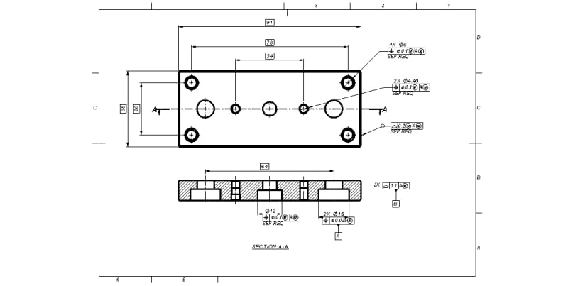
Finally we have concluded as below image.

070135_zpajoe.jpg


Assuming the DRF as below image

070135-1_uhtyjo.jpg


Thank you.
 
You have datum feature B designated by a symbol, but where do you use it?
If you do want to use it, and you want to treat the flat bottoms of the c'bores as coplanar features to derive a single datum plane from, you need a coplanarity control applied to them. Your perpendicularity tolerance doesn't do that.

There are other issues too but, one a time.
 
@Burunduk

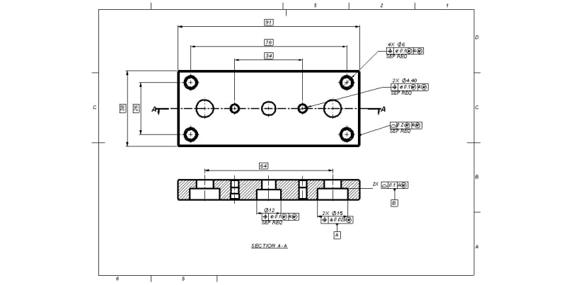
Drawing updated as per your suggestion.

070135_chiv7j.jpg
 
All around symbol added to profile of surface 0.2

070135_pzbyc0.jpg
 
Status
Not open for further replies.

Part and Inventory Search

Sponsor

Top