Continue to Site

Eng-Tips is the largest engineering community on the Internet

Intelligent Work Forums for Engineering Professionals

  • Congratulations waross on being selected by the Eng-Tips community for having the most helpful posts in the forums last week. Way to Go!

Three holes on same plane

Status
Not open for further replies.

Sa-Ro

Industrial
Jul 15, 2019
273
IN
Dear All

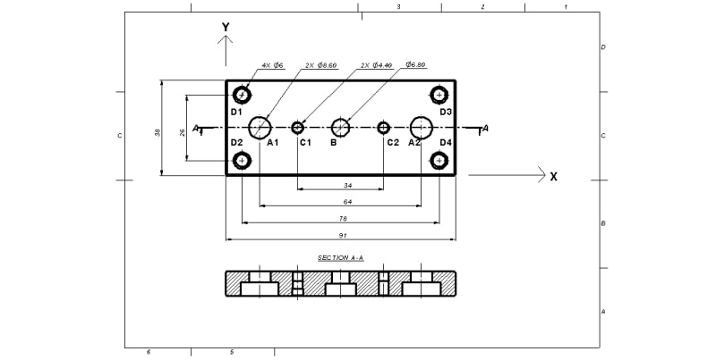
070135_tgnmnd.jpg


Our requirement:

1) Hole A1 and A2 shall be on same plane within variation of dia 0.05.

2) Hole A1 and A2 shall be symmetrical to hole B within variation of 0.05 along X axis.

3) Hole A1 and A2 shall be coincide with a plane passing thru hole B center axis within variation of 0.05 along Y axis.

4) Outer size 91 and 38 shall be aligned as shown in drawing.

5) Hole D1, D2, D3 and D4 shall be symmetrical to hole B within variation of dia 0.05

6) Hole C1 and C2 shall be on same plane within variation of dia 0.05.

7) Hole C1 and C2 shall be symmetrical to hole B within variation of 0.05 along X axis.

8) Hole C1 and C2 shall be coincide with a plane passing thru hole B center axis within variation of 0.05 along Y axis.

Kindly suggest us, how to define our requirement as per ASME Y14.5:2018 GD&T standard.

Thank you.
 
Replies continue below

Recommended for you

Looking at the picture of the cylinder, the counter ores don't seem to be locating features.

They're just counterbores for the screw heads.
 
I can't even see what's on the pictures.

By the way, if you're reinventing the pneumatic cylinder consider taking a look into existing catalogs.
What's your design intent with this? Are you copying an end plate or you're making a whole new complete cylinder?
Because when the machine maker buys the pneumatic component, he/she will likely position it to somewhere on his/her assembly. And by positioning the cylinder body it's likely that the end effector which will manipulate something need positioning also.

Take a look at the MGP type from SMC. The cylinder body has positioning holes on several flat surfaces for dowel pins. And that positioning translates through the guide rods to the end plate.
By your drawing your end plate isn't positioned at all, it has too much slop because the holes are clearence and not fitment.
 
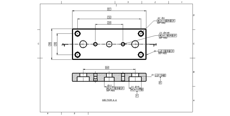
Sa-Ro said:
Drawing updated as per your suggestion.

You added the coplanarity control for datum feature B, but I still don't see where you reference it in a feature control frame of a geometric tolerance. If it is not used as a reference, the datum feature symbol for B is unnecessary.

Make sure the two c'bores you reference as datum feature A (primary) are really what constrains the location of the component in the assembly. As you may understand from my previous responses, I doubt it.
 
Hi

@ Mintjulep

Both counter bores are locating features only.

@Wuzhee

We are reverse engineering the end plate only, since it is a customer fitment in a replacement market.

As you mentioned, the positioning of end plate is taken care from the cylinder barrel and transferred thru two guide rods.

@ Greenimi

PDF drawing attached for better visibility.

@Burunduk

I missed to add datum B in respective FCF. Now added.

070135_bkz2t8.jpg


Thank you.

 
If all you're doing with datum feature B is referencing it as secondary for the holes and c'bores position tolerance and the all-around peripheral surface profile, then in my opinion it is not necessary at all.
 
If the counterbores are locating holes for the guide cylinders why don't they have tolerance on them?
Linear guide rods are precision machined to usually h5 or g6 tolerance. Making a fitment with untoleranced dimensions completely obliterates the whole reverse engineering. Just my last two or three cents.
 
@Burunduk
If we are not giving counter bore inner face as datum B, how to inspect the component for other holes and profile tolerances.

Because we need a face stopper to locate a component for rigidity.

Guiding the inner diameter alone means, the component may move along the hole axis.

That is what we assumed to have face stopper.

@Wuzhee
You are right about tolerance for holes.

We have mentioned basic dimensions in drawing for our discussion only.

Because our focus is to learn the correct methodology to represent our design requirements.

Thank you.

 
B used secondary does not bring anything to the control. Does not stop any relevant degrees of freedom of the tolerance zones. The TZ's are unchanged regardless if B is present (as secondary) or not.
Think about the TZ as cylinders parallel to each other and parallel with the DRF.....
 
our focus is to learn the correct methodology to represent our design requirements

That's why the first step is to understand how it fits with the mating parts. However little of what is shown is how a plate like this does that. The holes are secondary.

Before copying someone else's work understand what it does.
 
Sa-Ro,
See greenimi's comment. I totally agree with it. This is why datum feature B as secondary doesn't really help you. Since you selected the two side c'bores as primary, you have the 5 meaningful DOF for locating and orienting the holes and the peripheral edge surfaces already constrained. The question is - does it happen the same way in the real application of this part? As was pointed out several times in different responses you got in this thread, not only by me, it depends on the type of fit between the different c'bores and rods. Knowing what the tolerances on the different diameters are is important for understanding the application and selecting the datum scheme properly.
 
Greenimi said:
Does not stop any relevant degrees of freedom of the tolerance zones.

Tolerance zone of which dimension?

Greenimi said:
TZ's are unchanged regardless if B is present (as secondary) or not.

Accepted.

But without flat surface how to mount a component for inspection. Without datum B, component is free to move in Y axis.

3DDave said:
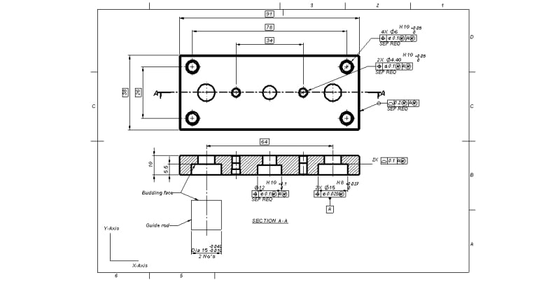
how it fits with the mating parts.

Image attached.

1_da7oqp.jpg


Burunduk said:
peripheral edge surfaces already constrained.

Which peripheral edges.

To all,

Now I understood.

Even though guide rod face and counter bore face are budding in assembly, if datum in FCF is not affecting the tolerance zone, the no need for that datum (in this case: datum B).

Cylindrical tolerance zone for holes and two parallel plane tolerance zone for outer rectangular shape is not affected by datum B.

So datum B shall be removed from drawing.

But, how to inspect the part.

I have mentioned datum A with material boundary modifier.

Gauge (two parallel pin) shall be dia 15 at 64 mm distance.

If I place the part on this parallel pin, the part will slide on dia 15 surface and rest on counter bore face.

But as per drawing, the counter bore face should not be located.

Did I conveyed something?
 
The virtual condition of the two ⌀15 c'bores is 15-0.025=14.975. The MMC of the parallel rods mating with them is larger than that. That means you might not be able to assemble them. Check carefully what is your actual locating features, what should be the size tolerances, and the datum selection.
It is difficult to locate a component with precision by a pattern of two internal cylindrical features, let alone if the intent is to maintain a sliding fit.

The peripheral edges are the "outer rectangular shape".
 
Thank you.

I will consider all your inputs.
 

Ø15 H8 is 'zero-plus'. +0,027/0

Sa-Ro,
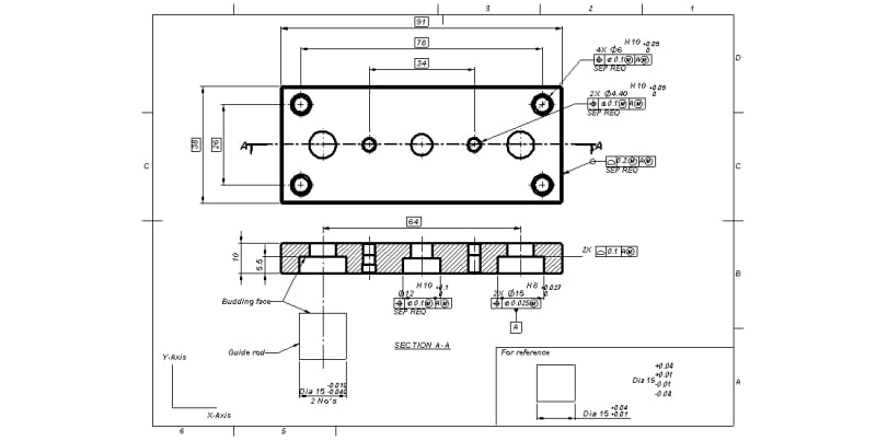
The guide rod tolerance should be swapped. The lower limit is the upper row, upper limit is the bottom row. So for the guide rod it's Ø15 -0,01/-0,04
 
That's backwards from how the typical install is done. But that's OK. I'm more impressed with the position tolerance diam 0.001 inch.

In the real installation the two linear guides are independent and do not form a single mating surface.

When the bolts are tightened the part will close the gaps with the two moving linear guide ends until the gap is eliminated, up to .4 degrees, not including the contribution from angularity of the rod ends.

There is enough clearance with the counterbores to allow up to .77 degrees, but it's possible the linear bearing rods will bind in the counterbores first.
 
@Wuzhee

Thanks for the input.

Refer the attached image.

1_k48wjw.jpg


Till date I assumed that lowest tolerance should be placed near to basic dimension.

One more doubt.

Can I use small letter tolerance for hole / Capital letter tolerance for shaft.

Normally small letter tolerance is used for shaft and capital letter tolerance used for holes.

Example:

Hole dia 10h8

Shaft dia 10H8

Is that right?
 

Never. Capital letters are for holes, lowercase for shafts.
Look into iso 286-2.
 
Status
Not open for further replies.

Part and Inventory Search

Sponsor

Top