Continue to Site

Eng-Tips is the largest engineering community on the Internet

Intelligent Work Forums for Engineering Professionals

  • Congratulations waross on being selected by the Eng-Tips community for having the most helpful posts in the forums last week. Way to Go!

tie-Contact problems with Abaqus

Status
Not open for further replies.

FantomasDA

New member
Jan 28, 2015
3
Hello guys,

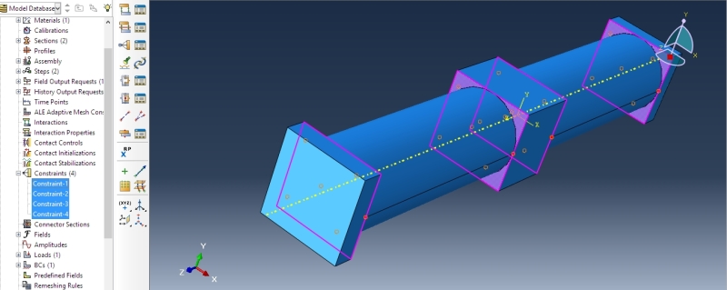
I am new on Abaqus and I have a problem with one of my project. I made an assembly with solid and two shelled cylinders.

I apply a pressure on the shelled cylinders. I tied the cylinders to the solids with the tool constraints (pic bellow)
hhhhhhhhh_apkmy7.jpg


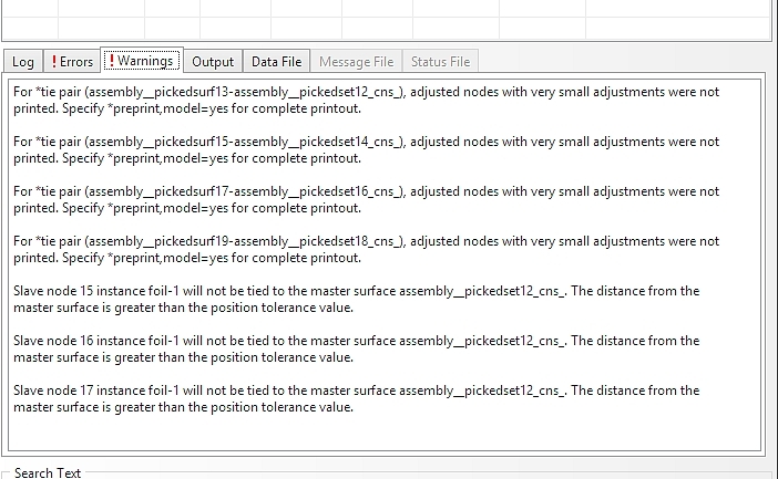
I have a problem when I start the analysis, there are errors that you can see with the next pic:
egsdgsdxvdf_xueq9q.jpg


I really don't know if it comes from the tie or something else...


Thx you for your interest


Best regards,

Dankoon
 
Replies continue below

Recommended for you

1. You posted a screenshot of the warnings, not the errors.
2. You should connect the shells to the solids with Shell-to-Solid-Coupling (Constraint in Interaction-Module). And you should create a separate constraint for each of your 4 connections.
 
Thx you very much Mustaine3 ! I changed the constraints to Shell-to-Solid Coupling and it's works! I have 0 warnings now.

Sorry I didn't post the screenshot of the errors. It's the next picture I have an error with my material..


gggggggggggffffffdfgdg_wqck3v.jpg


I read that I have to assign a local orientation in the material tool, should I do this for all the models?

Thx

Dankoon
 
Looks like your problem actually has to do with the material orientation since it is not isotropic. For each part/section that has the anisotropic material you need to assign which direction E11, E22, etc. are. It does not assume these align with any global or local coordinate systems.

In the Property Module go to Assign>>Material Orientation

There still could be issues with your constraints but you need to tackle this first. If you can't figure out which elements are having this issue you can usually open up the .odb and under element sets CAE creates a set called something like error_no_mat_orientation.
 
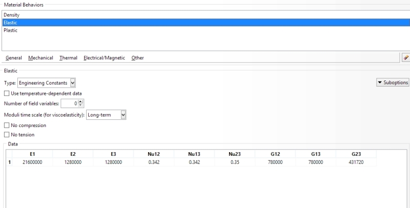
This is my material proprieties:

Sans_titre_3_h430mh.jpg


I don't know if it can help you.. I wonder on what I have to add an orientation...Sorry for my lack of knowledge I'm learning this alone..

Thx for your answers by the way!
 
Those material properties seem fine, but the material needs to have an orientation defined everywhere it is used. When you do your section assignments for each part or each partitioned region you will be in the "Property Module". This is where you need to assign the orientation of the material by doing...

In the Property Module go to Assign>>Material Orientation

Then follow the on screen commands to select which direction you want the material to be oriented. Then little triads will be placed on the model indicating the material orientation. Again this has to be done everywhere an anisotropic material is assigned.

I would also suggest making a copy of the model with the material being isotropic so that you can work on solving your tie-constraint problem while also working on the material orientation problem.
 
Status
Not open for further replies.

Part and Inventory Search

Sponsor