Continue to Site

Eng-Tips is the largest engineering community on the Internet

Intelligent Work Forums for Engineering Professionals

  • Congratulations IDS on being selected by the Eng-Tips community for having the most helpful posts in the forums last week. Way to Go!

Timber Pile Splice 2

Status
Not open for further replies.

jerseyshore

Structural
May 14, 2015
735
Within the last 6-12 months there has been a rush of "lifted house lifts" at the Jersey Shore. Typical house lifts are still happening at a normal pace, but because of the amount of water issues the barrier islands have now, houses that were already up 8'+ are now being raised an additional 1-3 ft. During these lifts the grade of the entire lot is getting raised up by the same amount to prevent the everyday rain/ bay water from flooding the ground floors.

Now this is typically done by cutting down the existing timber piles, installing a grade beam foundation, then building CMU/ concrete piers back up.

However, and as you can see in this picture below from a friend, engineers are signing off on timber pile splices like this now. How they justify this I have no idea and it's not something I have ever considered honestly. Seems like a waste of time to perform an analysis/ design just to find out it won't work anyway.

Most timber pile splice details I have seen are usually from DOT manuals for bridges and things of that nature.

Has anyone successfully detailed a timber pile splice like this and got it to work out on paper?
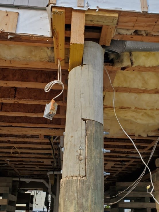
Re_pile_cflog5.jpg


(I love the overcuts from the circle saw on the splice piece, it adds a real nice touch of craftsmanship to the entire thing)
 
Replies continue below

Recommended for you

jerseyshore, Thanks for sharing this detail. I think I'm going to print it out just so I can crumple it up and throw it in the trash.

The capacity would be a little better with the 10" pile and 3/4" diam. bolts compared to my calculation. Maybe the bolts are good for 500 lbs each now (woohoo!). Not that that makes much of a difference. If we're strictly following NDS though, that end distance of 2" is technically not allowed since it's less than 3.5D = 2 5/8".

I'm sure in reality the splice can take a bunch more than what I calculated. I only based the capacity on the bolts, and I suppose there might be some useful friction between the pieces helping to resist the moment. Overall, this seems like a terrible detail. I wonder how the engineer justified it. Perhaps it's based on some sort of prescriptive method. Adding a knee brace would seemingly make sense.

For a lateral load in the other direction (left-right), the splice doesn't seem great for that either.
 
XR250, In my calcs. above I was assuming that the bolts are 4" apart and the center of bolt group is 3'-6" (raising the house by 3 ft). I also assumed the shear is split evenly between the 3 bolts, although that makes little difference here. If I had to guess, I think you're assuming the bolts are 6" apart. Either way, I think we're splitting hairs as we both seem to be arriving at the same conclusion.

If I update my numbers based on the detail above, with a 1,000 lb lateral force at the floor, and with the house being raised 3 ft (meaning center of bolt group is at 3'-6"), I get bolt forces of 4,630 lb, 333 lb, and -3,970 lb. If the bolt capacity is about 500 lb, then I think this is good for a little over 100 lbs lateral per the detail.

 
And per ChorasDen's point above regarding moisture content, I think it's possible that CM = 0.4 might even apply here. The PT wood will almost certainly have mc > 19% at time of fabrication and it seems possible that it could have mc <= 19% in service. Maybe that's going too far!
 
I have helped erect Ag buildings where we spliced major columns.
Often it was because we buried PT material and then transitioned to non-treated above grade (usually 3-5' up).
But these were square and laminated.
So typically say 3 @ 4" x 12" joined outside the splice with RSPB spikes.
And then the joint was staggered, one side at nominal height, middle at -1', and the other side at +1'.
We would slide them together and join with 8 @ 3/4" bolts (two rows of 4) through the whole thing (3" from ends and edges).
We never questioned the strength of these joints.

= = = = = = = = = = = = = = = = = = = =
P.E. Metallurgy, consulting work welcomed
 
XR250 said:
I've been in a few beach houses that I could feel moving side to side from just humans walking around.

I have inspected many of these; went to one just a couple of months ago. There are many "ranches" that were built on 3 pile wide layouts with no perpendicular band beams. Just one person walking around can move the house back and forth. Those require additional band beams and usually X-bracing in the short direction.

XR250 said:
Looks like they were adding a slab at the bottom which may help with the pile's moment capacity

The slab is a frangible (breakaway) slab so yes it will help for the average day, but during a flood it can't be relied on technically.

Eng16080, thanks for the calcs. There are thousands of these houses under construction right now all along the shore and it's doubtful anyone actually runs any numbers on these connections. I know I rarely do unless I need to do a retrofit or check for uplift. Obviously this is a bit of unique situation since it's a moment connection.

One thing I'm hoping was done correctly at least was upsize the bolt diameter because based on the detail it appears that they re-used the upper two existing holes. Anyone that does work with these types of timber piles knows how much shrinkage can happen around these bolts over the years. This house is only 10 years old so it might not be an issue here, but these connections can get loose easily.
 
Status
Not open for further replies.

Part and Inventory Search

Sponsor