Eng-Tips is the largest engineering community on the Internet

Intelligent Work Forums for Engineering Professionals

  • Congratulations waross on being selected by the Eng-Tips community for having the most helpful posts in the forums last week. Way to Go!

Timber roof on a RC concrete slab.

Status
Not open for further replies.

kellez

Civil/Environmental
Nov 5, 2011
276
CY
Hi,

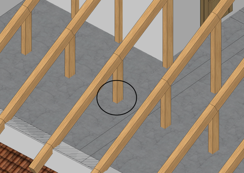
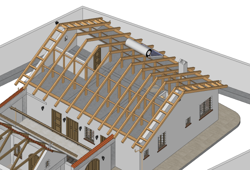
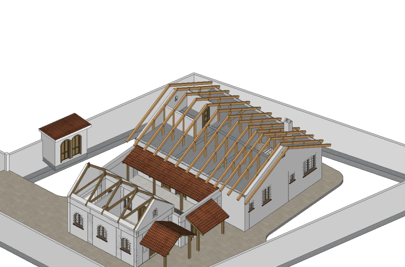
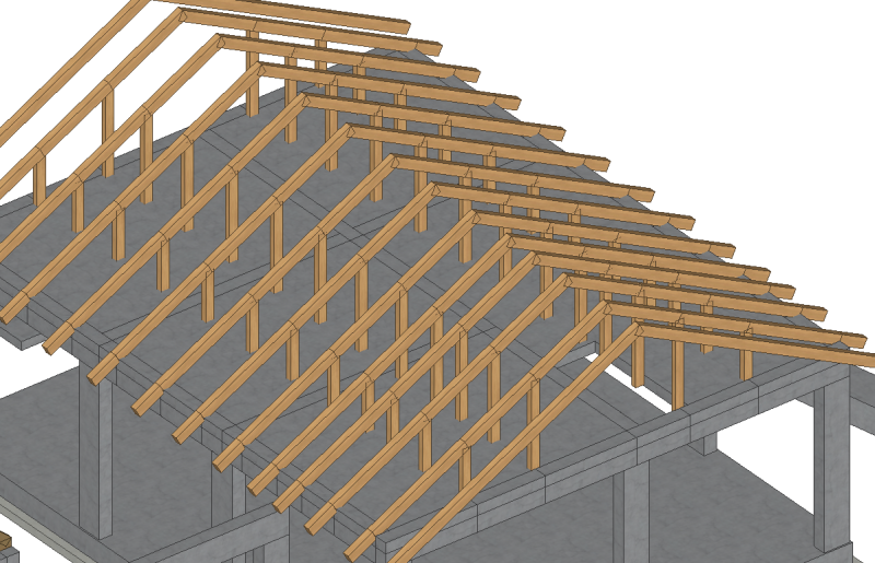
I am designing a timber roof to be supported by a RC concrete slab. As you can see from the picture the timber frame is simply composed
of inclined beams supported by timber columns that connect to the RC slab.

Now my question is, what is the best way to connect the timber columns to the Rc slab? I am thinking of steel brackets but not really sure.
Screen_Shot_2017-10-18_at_10.35.29_wgqqyc.png

Screen_Shot_2017-10-18_at_10.48.00_m7r0bs.png

Screen_Shot_2017-10-18_at_10.36.09_rs7nv5.png
 
Replies continue below

Recommended for you

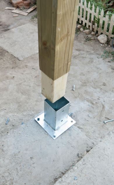
Hi, You can anchor your timber posts to concrete floor as below.
Capture0_cyk4xp.jpg

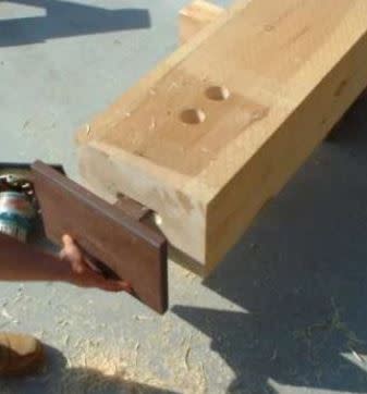
Also you can make a slot at the bottom of your post and connect using steel connectors as below.
Capture01_vfcmsw.jpg
 
I'd go with a Simpson post base, like the ABA...link These are available in N America and elsewhere.

A 'U' shaped steel bracket would also work, or simply steel angles anchored to the floor and post base, as long as you can avoid direct contact between raw wood and concrete.
 
I've used the lower one for concealed fasteners with 2 - anchor rods into the concrete. all hidden... worked well. Any chance you can make those timber roof members into trusses and cut back on some of the vertical elements?

Dik
 
Thank you everyone, i think i will go with something similar to Simpson AB base.

kipfoot said:
A 'U' shaped steel bracket would also work, or simply steel angles anchored to the floor and post base, as long as you can avoid direct contact between raw wood and concrete.

One more question is it really necessary to keep the timber out of contact with the concrete in a location such as the roof slab?

dik said:
Any chance you can make those timber roof members into trusses and cut back on some of the vertical elements?

Initially my design was composed of roof trusses but the client changed his mind and asked for usable roof space, therefore i left an empty space in the middle of 2.50m.
I decided to also remove the bottom chord of the truss so that the concrete slab can be used as the floor without worrying about the bottom chord.

Having removed the bottom chord and all diagonal bracing form the truss, I now have only vertical elements, which i think is not sufficient to provide the required lateral stability of the frame.
I now need to think of a way to provide additional lateral support to the frame, i think my options are

1) Decide on the direction of the connection of the timber post with the concrete slab.
2) Decide on the connection between the timber post and timber chord (beam)
3) Decide on the connection where the two timber beams meet at the peak
4) Add diagonal bracing between the two timber posts.


As long as the rafters are attached to the slab at the roof edge and you have a roof diaphragm, you are stable.

added edit - and it would be helpful to have collar ties above the center two posts
 
Can you put a couple of supports at the roof with a beam at the ceiling level and maybe a couple of columns supporting the ceiling beam. A large number of posts on the main floor will quickly become a pain...

Dik
 
dik said:
Can you put a couple of supports at the roof with a beam at the ceiling level and maybe a couple of columns supporting the ceiling beam. A large number of posts on the main floor will quickly become a pain...

Dik

Hmmm, i see what you mean, too much drilling on the main floor...currently i have 48 timber posts that need to be fixed on the concrete floor.Too much drilling and too many Simpson bases
I think i need to halve that.

Ok so you are suggesting to use a main beam running from one gable wall to the other gable wall with a couple of timber posts for support.
what do you suggest i do with the current 48 timber posts? shall i keep only one in the middle of the main rafter?


You probably need a ridge board as well.

I would replace the lines of columns with lines of beams, then support said beams at a minimum 8ft on center. The exterior rafter eave condition will probably need a (2)2x6 PT nailer. Then use hurricane ties here.
 
EngineeringEric said:
You probably need a ridge board as well.

due to the fact that the client asked for a usable space, instead of using a ridge board (that needs timber posts in the middle of the roof)
i decided to use bracing connecting all rafters to one another (see picture, its an update of the original design). Additional bracing will also be provided by OSB sheathing.

However I will have to reconsider the design due to big number of timber posts used.

EngineeringEric said:
I would replace the lines of columns with lines of beams, then support said beams at a minimum 8ft on center. The exterior rafter eave condition will probably need a (2)2x6 PT nailer. Then use hurricane ties here.

I will consider this with my new design.

Screen_Shot_2017-10-18_at_21.47.21_dre7oy.png
 
Too many posts cluttering up the floor space...

Dik
 
dik said:
Too many posts cluttering up the floor space...

Yes this is the main issue with my design above, I will try to reduce the number of timber posts.

Now i see were I went wrong with the design...I actually tried to reproduce the design of a trussed rafter but removing certain components that actually were not required due to the concrete slab below and i ended up with too many posts that need to be fixed on the concrete floor which is too much work.

 
Kellez:
Cast a 6" wide by 3.5" high curb with and around the RC slab. That uses a 2x4 for the inside forming. Then use 2x8's (dimensional lumber) for roof rafters at 24" o/c, with a ridge board. The rafters have a vert. plumb cut and a horiz. bearing seat cut to fit the curb and slab, and distribute their vert. and thrust reactions. Scab on 2x4 or 2x6's as tails for the eave overhang. At the gable ends, set the first interior rafter and the gable end framed walls 3.5" lower than the roof plane of the other rafter tops. Then build a 2x4 ladder which cantilevers out for the rake soffit and trim. Since you didn’t bother to tell us anything about loads, building dimensions, all the important design info. the above is for concept only. Why not give that important design info. if you want meaningful answers, remember we can’t see exactly what you’re thinking. What training, and experience do you have, and where did you get it, regarding structural design in wood and concrete and their construction methods?
 
Why not just use a typical stud bearing wall on each side of the 2.5 metre wide usable space? Just bolt down the bottom plate, and tie the studs and rafters down as you would for any typical wall.
 
dhengr said:
Why not give that important design info. if you want meaningful answers, remember we can’t see exactly what you’re thinking. What training, and experience do you have, and where did you get it, regarding structural design in wood and concrete and their construction methods?

Hi dhengr, I have an MSc in Civil Engineering and the only experience I have is with RC concrete structures and seismic design of RC structures. I have not designed a timber roof before and i have not seen anything up close similar to the one i am designing. However, I can do the modeling analysis and design once i decide on the layout of the roof.

New Design

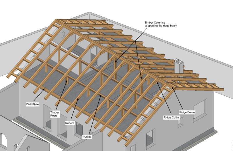
After all the comments I have changed my design

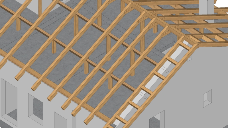
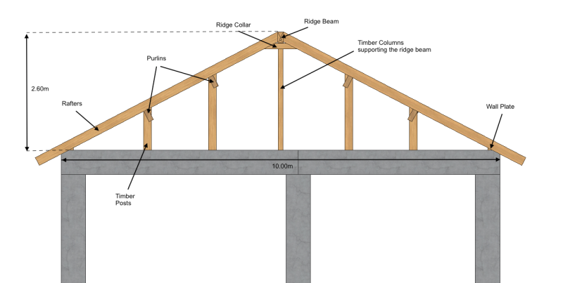
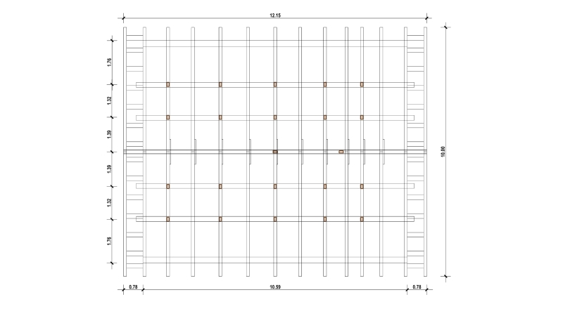
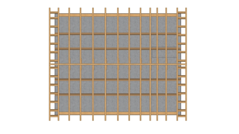
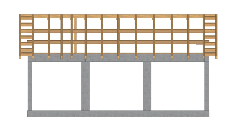
As you can see I have used purlins to support the weight of the rafters and reduced the number of timber posts which support the timber purlins.
Now I have 20 timber posts instead of 48 as with the old design
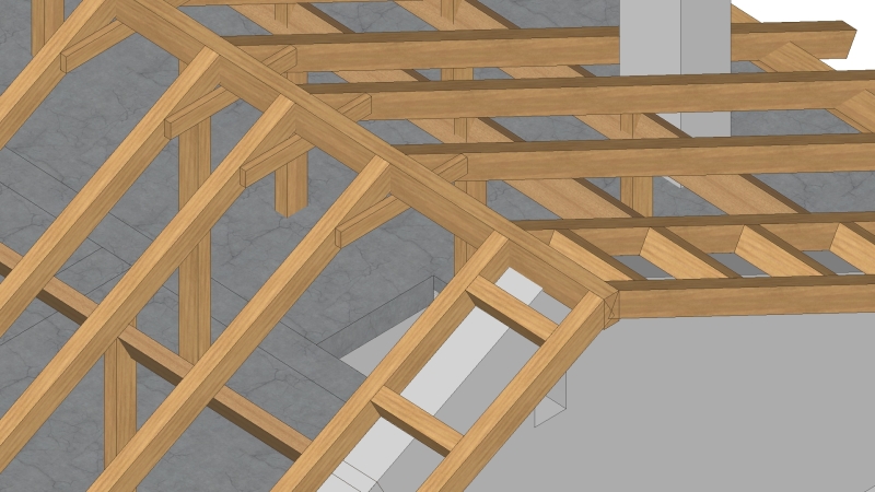
I have also included a ridge beam with ridge colar which is supported by timber columns, Please have a look at the pictures below.

What you guys think about the new design, can you see any major issues? Please, guys, try to help me out a bit more with your advice, i really need your help with this one.


Roof Dimensions

Roof Length = 12.15m
Roof Width = 10.00m
Roof Height = 2.60m

Loadings on the roof are:

Permanent Loads:
1. Selfweight of timber frame
2. Roof coverings = 0.93kN/m2

Wind Loads
3. Wind Pressure = 0.80kN/m2
4. Internal wind pressure = 0.15kN/m2

Imposed Loads
5. Roof (Category H) = 0.4kN/m2


Screen_Shot_2017-10-23_at_11.12.29_wjkbke.png

MONASTIRI_v10_-_Structural_Model_-_29_-_Timber_Roof_Design_2a_ScreenShot_23102017_200525_pchm8u.jpg

MONASTIRI_v10_-_Structural_Model_-_29_-_Timber_Roof_Design_2a_ScreenShot_23102017_200731_unlmzx.jpg

Screen_Shot_2017-10-23_at_11.10.01_ynpjmt.png

Roof_-_Plan_View_ongkx1.jpg

MONASTIRI_v10_-_Structural_Model_-_29_-_Timber_Roof_Design_2a_ScreenShot_23102017_185033_ohmm5u.jpg

MONASTIRI_v10_-_Structural_Model_-_29_-_Timber_Roof_Design_2a_ScreenShot_23102017_190305_v1ebaz.jpg
 
Kellez:
Do you have roof sheathing material which will span about 4' (12.15m/10)? Why are you insisting on some form of timber framing, wouldn’t stick framing with dimensional lumber be less expensive and less complicated? Why not put a framed bearing wall at about the quarter point of the roof span, about 8' from the exterior rafter bearing (10m/4)? At this location, you are pretty much out of useful headroom up in that space, with only about 4' clearance. Then frame the roof with 20' - 2x8's, or some such, at 2' o/c, and continuous over the framed bearing wall; or two 2x8's, lap spliced over the bearing wall. Full length, 20' +/-, I-Joists would work for the rafters too. Now, the center part of the space can be column free, a much more useable space, and you really only need a ridge board up at the ridge. The framed bearing wall has studs at 2' o/c, and can have a couple 4' openings with a header for access into the outer storage space under the exterior portion of the roof. You must pick up some roof framing thrust and other lateral loads out at the exterior bearing line.
 
First of all thanks a lot for your time, I really appreciate this, i have learned a lot from these Forums and its people like you that make this such a great place. Thank you


dhengr said:
Why not put a framed bearing wall at about the quarter point of the roof span, about 8' from the exterior rafter bearing (10m/4)? At this location, you are pretty much out of useful headroom up in that space, with only about 4' clearance.

Ok i understand that you want me to remove the 2 purlins that run across the two gable walls and replace them with a load bearing stud wall at a quarter of the roof span 10/4m = 2.5m


dhengr said:
Do you have roof sheathing material which will span about 4' (12.15m/10)?

dhnegr said:
Then frame the roof with 20' - 2x8's, or some such, at 2' o/c, and continuous over the framed bearing wall; or two 2x8's, lap spliced over the bearing wall. Full length, 20' +/-, I-Joists would work for the rafters too.

You also want me to increase the number of rafters (and decrease their size) so that the span for the OSB board is also reduced.

dhengr said:
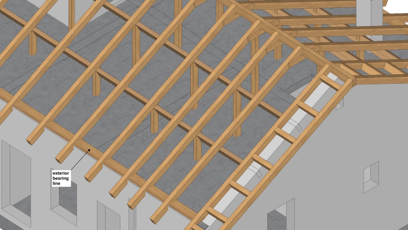
You must pick up some roof framing thrust and other lateral loads out at the exterior bearing line.
I did not quite get that, by exterior bearing line you mean where the rafters sit in the RC slab? (see picture below)

MONASTIRI_v10_-_Structural_Model_-_29_-_Timber_Roof_Design_2a_ScreenShot_23102017_200525_copy_scgf51.jpg
 
Given the owner's desires regarding space usage, I'd get rid of the columns beneath the ridge and let the rafters cantilever up to a ridge board that is supported by the cantilevers without the posts.

I like to debate structural engineering theory -- a lot. If I challenge you on something, know that I'm doing so because I respect your opinion enough to either change it or adopt it.
 
Status
Not open for further replies.

Part and Inventory Search

Sponsor

Back
Top