Continue to Site

Eng-Tips is the largest engineering community on the Internet

Intelligent Work Forums for Engineering Professionals

  • Congratulations KootK on being selected by the Eng-Tips community for having the most helpful posts in the forums last week. Way to Go!

Timber to Timber cantilever connection 3

Status
Not open for further replies.

Aleeeex

Civil/Environmental
Aug 14, 2020
42
Hi,

This is really uncommon to me however I have tried my upmost and was wondering if you would share your thoughts.

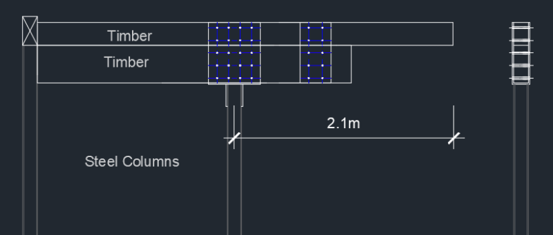
I have 2 different sized timber beams cantilevered both which are supported by steel column. The top timber beam overhangs the bottom with a distance of 2.1m from the steel column. I have come up with the following connection. I used 20 M12 and the utilization is 0.89.

I have checked the following

1- bolts capacity perp to the grain
2- timber beams tensile stress along the grain, and shear stresses.
image_rvvqlu.png


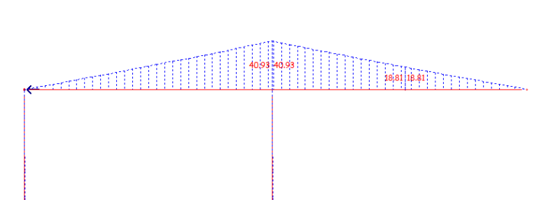
Bending Moment

image_zc5sxa.png


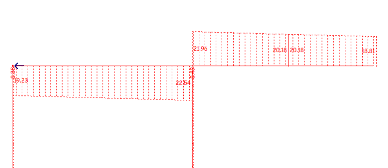
Shear

image_t91c9x.png


Thank you for your input.
 
Replies continue below

Recommended for you

AndyWat,

The load of 165 kN seems excessive to me. Check your calculations and see the comment by jayrod12.

BA
 
BA Retired! If I wasn't aware of an issue I would not resort to this forum. So I am here seeking HELP!

I am fully aware about the tension at plate No 2.

image_pexp2d.png


As I mentioned in my first post this is uncommon to me.

Please if you are not willing to help and be polite then please do not comment.

Thank you
 
Is it possible to glue the beams and use bolted side plates?

Thank you
 
AndyWAT said:
BA Retired! If I wasn't aware of an issue I would not resort to this forum. So I am here seeking HELP!

I am fully aware about the tension at plate No 2.

If you are fully aware of the issue, then you should realize that you have not provided adequate information for anyone to provide an intelligent response. You have not mentioned the size of the beams in question or the material. Thus, we do not know their relative stiffness. And you do not show dimensions. Are you expecting us to scale them?

There is no need for the plate near point 3 other than to keep the two beams in position. Why you would need 12mm plates is a mystery.

There is not necessarily a need for the connection at point 2, other than two keep the beams in position and possibly to reduce the gap between them when load is applied. Again, 12mm plates seems like overkill to me.

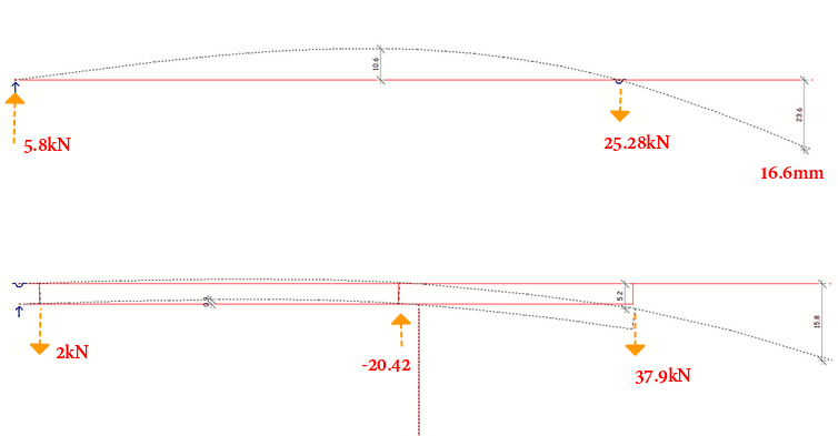
I don't know of what you are aware. You do not appear to be aware that your first sketch shows a mixture of reaction forces, which are wrong, and a deflection, which may be correct...who knows?

Your second diagram shows three forces which cannot be correct, assuming the drawing is roughly to scale.


AndyWAT said:
As I mentioned in my first post this is uncommon to me.

Please if you are not willing to help and be polite then please do not comment.

If this type of design is uncommon to you, you should seek help other than a forum with answers from complete strangers. I am usually willing to help, but not when I believe my help may lead to danger to others. I consider my comments thus far to be perfectly polite and I will continue to comment further as deemed appropriate. If you don't like it, that is your problem.

BA
 
AndyWAT, why in the world would you glue the beams AND use bolted side plates. The glue would be continuous and stiffer than the side plates. The side plates would be discreet and less stiff than the glue. Achieving consistent deformations between the two different fastening systems would be practically impossible, resulting in the side plates doing absolutely no work unless the glued joint failed.
 
AndyWAT said:
Is it possible to glue the beams and use bolted side plates?

Certainly it is possible. Whether or not it is necessary is another matter. One question you might ask yourself is "Do I need the beams to act compositely?"

BA
 
I think the simplest way is to analyze and design the stacked beams as a composite/built-up beam. The glue, or connection plates, shall be able to resist the shear flow at the interface. If plates are chosen, I suggest adding one at far left side, and one in between the two supports, to better distribute the stress. I am not a wood guy, so it is up to you to find the best way to connect the timber beams.

image_bu8ndu.png
 
The back-span dimension is not given, but it appears to be shorter than the 2.1m cantilever. If so, the left hand reaction will be an uplift larger than the applied load; and the right hand reaction with be larger than twice the applied load.

BA
 
Post all the dimensions: backspan of each beam, cantilever of each beam, section sizes, type of timber (sawn, LVL etc). Then you can get some real help.
 
I can not see any issue with the connections if you are using M12 and 10mm plate thickness.

If you are not 100% confident just glue them!
 
If you are using glulam beams, why not have the fabricator build a single beam with the shape requested by the client? That would be much easier to analyze.

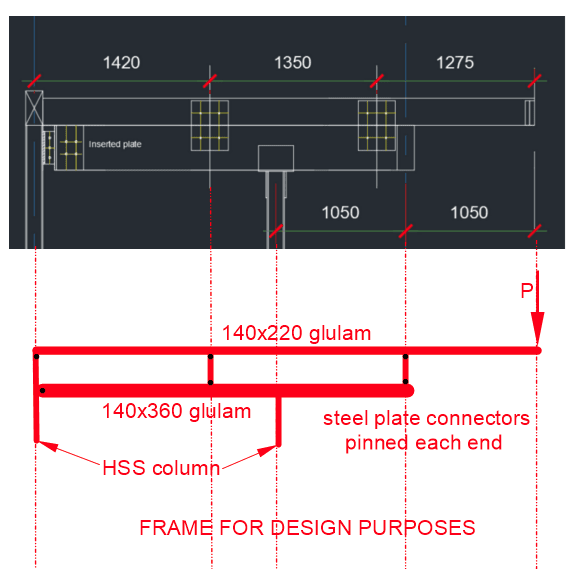
As it is, you have performed an analysis of the top beam. I don't know if you assumed level supports in carrying out your analysis. If so, a better solution would be to consider a frame as shown below which would take into account deflection of the lower beam.

If you find the two beams deflecting into each other, you need to correct your assumptions. The simplest way to do that would be to add a virtual member at the mid-points of the conflict. (A virtual member does not require plates or bolts; it simply recognizes that the beams are bearing against each other.)

image_nnnmue.png


BA
 
I don't understand the purpose of the inserted plate nearest the left hand column. I would have thought you would use a beam hanger, recognizing that the lower beam reaction is up, not down, which means that your bolts would be working in double shear.

BA
 
Thank you BARetired

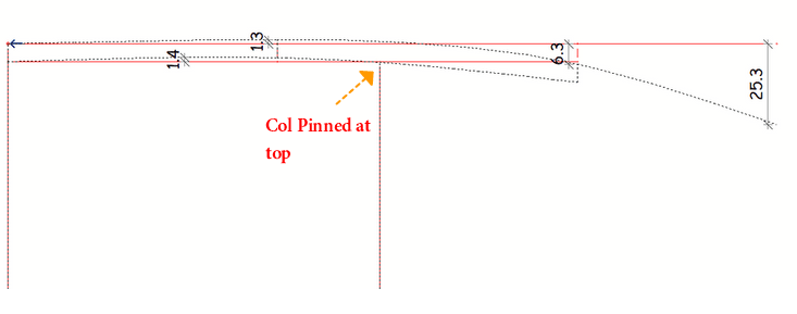
I followed your suggestion and I am getting a deflection of 25.3mm service load. To me it is a bit high. Can you explain further about identifying a virtual member please.

image_bwbf4t.png
 
Aleeex said:
I followed your suggestion and I am getting a deflection of 25.3mm service load. To me it is a bit high. Can you explain further about identifying a virtual member please.

A virtual member is a non-existent member which must be introduced where two members are bumping into each other. Suppose, for example the upper beam is found to deflect upwards by 10mm and in the same location, the lower beam deflects upward by 15mm. This can't happen, so you introduce a virtual member between the beams to force equal upward deflections in the two beams. There is no need to place a real member in that location as the beams bear against each other.


BA
 
Aleeex,

Try model the beam with varying moment of inertia. If it is still deflect too much, you need to upsize the upper beam. If the resulting deflection at the tip of the cantilever, and the bowing in between the supports are both acceptable, just find ways to connect the beams and design the connectors using shear flow equation.
 
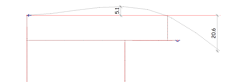
I manged to bring the deflection to the acceptable limit.

image_xcl1eq.png


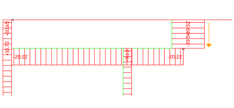
My question is do I need to design these connections based on these axial forces.

image_dlztb0.png
 
Have you added a support to the tip of the lower cantilever? That deflection diagram doesn't look right.

Does that plate in the back span need to be where you have it? You might get a better result by (re)moving it.
 
Yes I added support because there is another cantilever attached. So the deflection is right 100%.
 
You like keeping secrets, don't you? Can this 3rd cantilever support the upper cantilever without the lower cantilever?
 
The deflection is increased a little bit

image_pahoj4.png


image_dmycz1.png
 
Status
Not open for further replies.

Part and Inventory Search

Sponsor