Aleeeex
Civil/Environmental
- Aug 14, 2020
- 42
Hi,
This is really uncommon to me however I have tried my upmost and was wondering if you would share your thoughts.
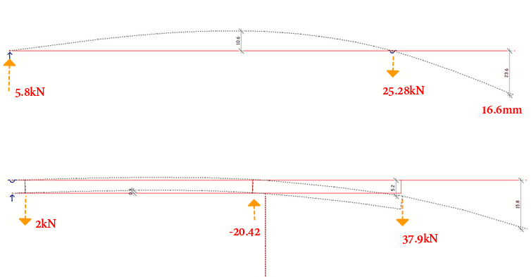
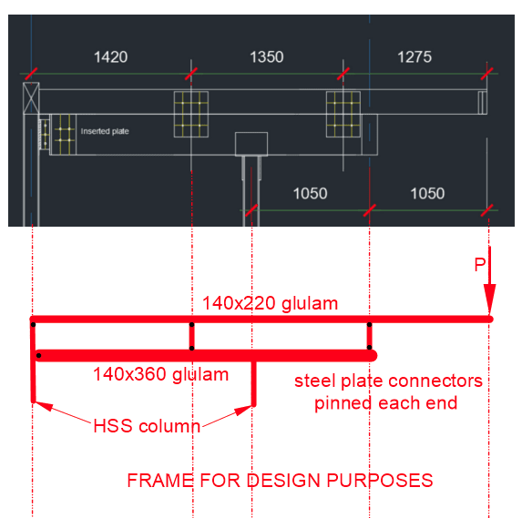
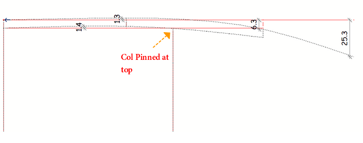
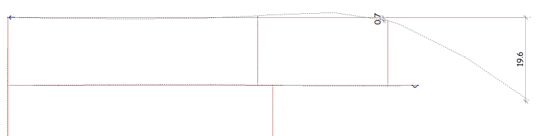
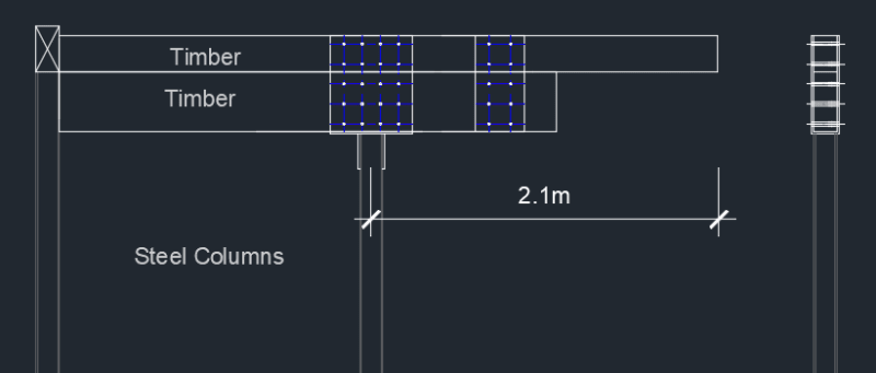
I have 2 different sized timber beams cantilevered both which are supported by steel column. The top timber beam overhangs the bottom with a distance of 2.1m from the steel column. I have come up with the following connection. I used 20 M12 and the utilization is 0.89.
I have checked the following
1- bolts capacity perp to the grain
2- timber beams tensile stress along the grain, and shear stresses.
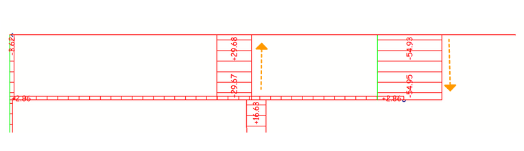
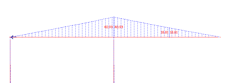
Bending Moment
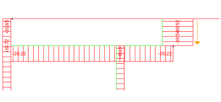
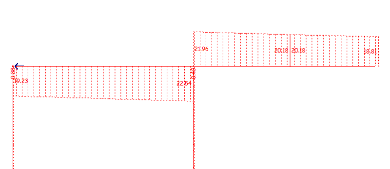
Shear
Thank you for your input.
This is really uncommon to me however I have tried my upmost and was wondering if you would share your thoughts.
I have 2 different sized timber beams cantilevered both which are supported by steel column. The top timber beam overhangs the bottom with a distance of 2.1m from the steel column. I have come up with the following connection. I used 20 M12 and the utilization is 0.89.
I have checked the following
1- bolts capacity perp to the grain
2- timber beams tensile stress along the grain, and shear stresses.
Bending Moment
Shear
Thank you for your input.